Difference between revisions of "VAXstation 100 firmware notes"
(→RAM memory map: Some more RAM locations.) |
(Communication.) |
||
| Line 190: | Line 190: | ||
This icon is displayed when there's a communication problem.<br> | This icon is displayed when there's a communication problem.<br> | ||
[[Image:VS100-Unable.png]] | [[Image:VS100-Unable.png]] | ||
| + | |||
| + | ==Communication== | ||
| + | |||
| + | The firmware communicates with the host through a set of eight 16-bit registers. (There is also a 256K window into the host Unibus address space.) | ||
| + | |||
| + | These registers are written. | ||
| + | {| class="wikitable | ||
| + | | CSR0 | ||
| + | | Bit 0 - clear "go" bit. | ||
| + | |- | ||
| + | | CSR1 | ||
| + | | Interrupt reason. | ||
| + | |- | ||
| + | | CSR2 | ||
| + | | Peripheral event. | ||
| + | |- | ||
| + | | CSR3+CSR4 | ||
| + | | Unibus window address. | ||
| + | |- | ||
| + | | CSR5 | ||
| + | | Firmware version. | ||
| + | |- | ||
| + | | CSR6 | ||
| + | | BBA info. | ||
| + | |} | ||
| + | |||
| + | These events are sent. Numbers are hexadecimal. | ||
| + | {| class="wikitable | ||
| + | | 0000 | ||
| + | | | ||
| + | |- | ||
| + | | 0001 | ||
| + | | Function performed ok. | ||
| + | |- | ||
| + | | 0002 | ||
| + | | Command performed ok. | ||
| + | |- | ||
| + | | 0008 | ||
| + | | Mouse buttons. | ||
| + | |- | ||
| + | | 0080 | ||
| + | | | ||
| + | |- | ||
| + | | 8000 | ||
| + | | Function error. | ||
| + | |- | ||
| + | | 8001 | ||
| + | | Bad function number. | ||
| + | |- | ||
| + | | 8002 | ||
| + | | Bad command number. | ||
| + | |} | ||
| + | |||
| + | These registers are read. | ||
| + | {| class="wikitable | ||
| + | | CSR0 | ||
| + | | Bit 0 - check "go" bit. Bits 1-5: function code. | ||
| + | |- | ||
| + | | CSR3+CSR4 | ||
| + | | Parameter. | ||
| + | |} | ||
| + | |||
| + | These functions are implemented in ROM. Numbers are decimal. | ||
| + | {| class="wikitable | ||
| + | | 1 | ||
| + | | Init - setup hardware. | ||
| + | |- | ||
| + | | 2 | ||
| + | | Command - further decoded. | ||
| + | |- | ||
| + | | 3 | ||
| + | | Start firmware - parameter is address. | ||
| + | |- | ||
| + | | 5 | ||
| + | | Reset. | ||
| + | |- | ||
| + | | 18 | ||
| + | | Clear infinite retry counter. | ||
| + | |- | ||
| + | | 19 | ||
| + | | Clear finite retry counter. | ||
| + | |} | ||
[[Category: DEC Software]] | [[Category: DEC Software]] | ||
Revision as of 10:33, 27 February 2023
Some random notes from running the DEC-supplied standard firmware for the VAXstation 100 in an emulator.
The firmware analyzed announces itself as version 05.00. It deviates in minor details from the information in the 1983 "VS100 Engineering Specification".
Contents
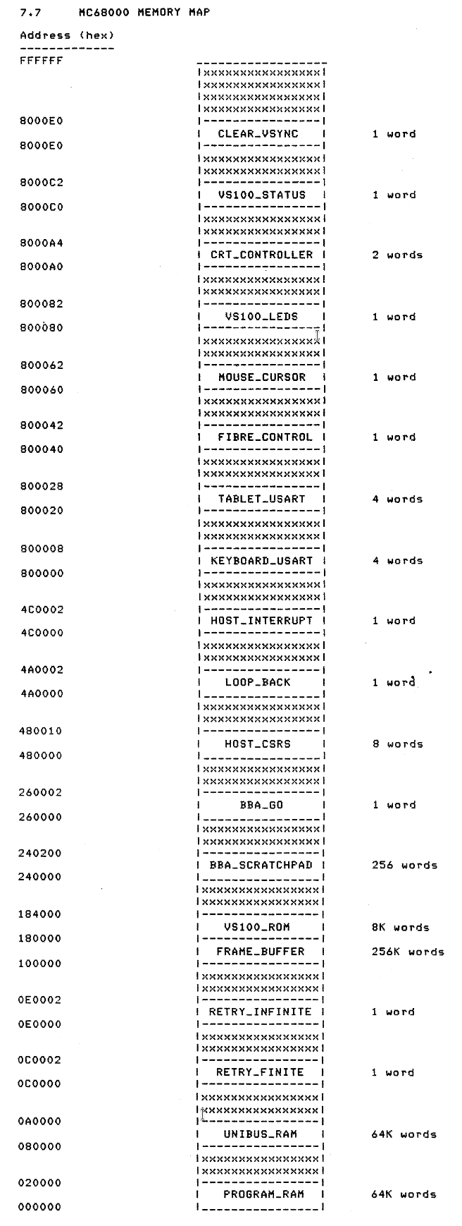
Memory map
Firmware 5.00 extends the LOOPBACK region to one more word at 4A0004. Apparently this loops back the value written to 480004.
The BBA scratchpad has been moved to 30000. An accesses to a byte at 280000 seems to clear a BBA interrupt.
RAM memory map
Most of the RAM is available for uploaded software. However, regions at the ends are used by the ROM for fixed purposes:
| 000000 | 32 longwords | Exception vectors |
| 000080 | 15 longwords | Saved screen contents under mouse pointer |
| 0000C0 | two words | Mouse x,y copied from hardware register |
| 0000C4 | two words | Old mouse x,y screen coordinates |
| 0000C8 | two words | New mouse x,y screen coordinates |
| <01FFC0 | extends towards lower addresses | Stack |
| 01FFC0 | one longword | Keyboard fifo read pointer |
| 01FFC4 | one longword | Keyboard fifo write pointer |
| 01FFC8 | one longword | Tablet fifo read pointer |
| 01FFCC | one longword | Tablet fifo write pointer |
| 01FFD0 | one word | Cursor column |
| 01FFD2 | one word | Cursor line |
| 01FFD4 | Connection timeout counter | |
| 01FFD6 | 16 bytes | Keyboard output fifo |
| 01FFE6 | 16 bytes | Tablet output fifo |
| 01FFF6 | one byte | Size data in keyboard fifo |
| 01FFF7 | one byte | Size data in tablet fifo |
| 01FFF8 | one byte | Mouse buttons |
| 01FFF9 | one byte | Keyboard input (LK201 code) |
| 01FFFA | one byte | Tablet input |
| 01FFFB | one byte | State of CTRL and SHIFT, for entering maintenance menu |
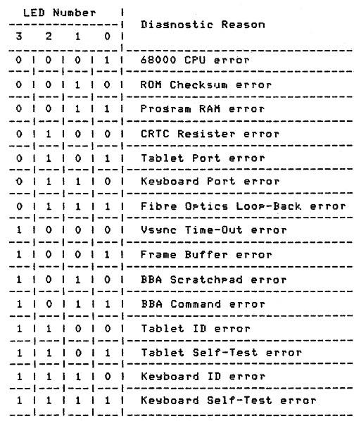
Error LEDs
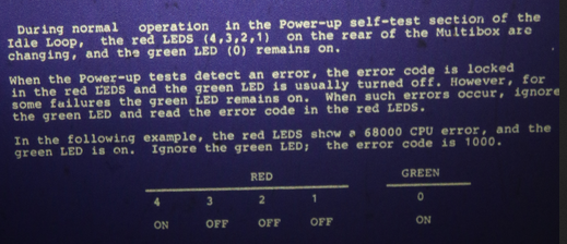
Indicates which test failed. During power-up, green light turned off. During idle loop, green light remains on.
Apparently there's a bug.
Interrupts
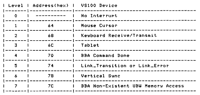
All VS100 interrupts use the autovector feature.
Firmware 5.00 doesn't use the level 1 interrupt. The firmware only reads the mouse position during maintenance test.
Keyboard test
The firmware transmits code FD (hex) to the LK201 keyboard, which commands it to jump to the power-up sequence and self-test. The keyboard transmits a four-byte message back. The VS100 ignores the keyboard ID, and checks that the third is not 3D.
This information is from the VT220 Technical Manual.
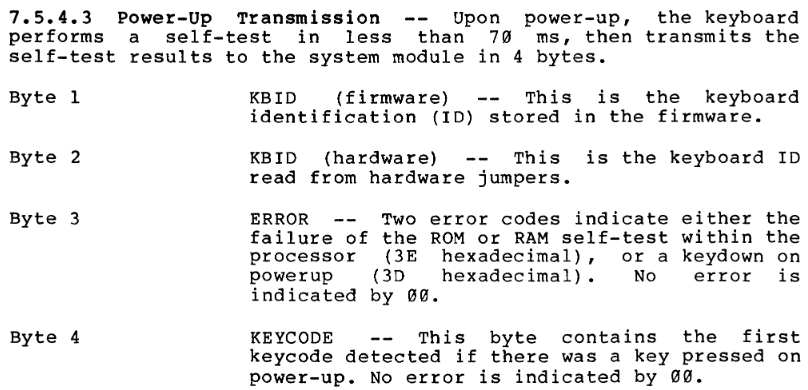
D0 flags
The firmware maintains a set of flags in register D0.
| Bit (decimal) | Meaning |
| 16 | Manufacturing mode. |
| 17 | BBA present. |
| 18 | Link down. |
| 19 | Power-up error. |
| 20 | LEDs locked. |
| 21 | Suppress printing test result. |
| 22 | In maintenance menu. |
| 23 | Keyboard ok. |
| 24 | BBA done. |
| 25 | Vertical retrace interrupt. |
| 26 | Test not executed. (E.g. hardware not present.) |
| 27 | Test timed out. |
| 28 | Host wants attention. (Same vector as TRAP #1?!?) |
Built-in graphics
The firmware has a mouse pointer, a text font, and three icons. The first two are straight bitmaps, whereas the icons are run length encoded.
This icon is displayed when a user can be logged into the system.

This icon is displayed when there's an internal error.

This icon is displayed when there's a communication problem.

Communication
The firmware communicates with the host through a set of eight 16-bit registers. (There is also a 256K window into the host Unibus address space.)
These registers are written.
| CSR0 | Bit 0 - clear "go" bit. |
| CSR1 | Interrupt reason. |
| CSR2 | Peripheral event. |
| CSR3+CSR4 | Unibus window address. |
| CSR5 | Firmware version. |
| CSR6 | BBA info. |
These events are sent. Numbers are hexadecimal.
| 0000 | |
| 0001 | Function performed ok. |
| 0002 | Command performed ok. |
| 0008 | Mouse buttons. |
| 0080 | |
| 8000 | Function error. |
| 8001 | Bad function number. |
| 8002 | Bad command number. |
These registers are read.
| CSR0 | Bit 0 - check "go" bit. Bits 1-5: function code. |
| CSR3+CSR4 | Parameter. |
These functions are implemented in ROM. Numbers are decimal.
| 1 | Init - setup hardware. |
| 2 | Command - further decoded. |
| 3 | Start firmware - parameter is address. |
| 5 | Reset. |
| 18 | Clear infinite retry counter. |
| 19 | Clear finite retry counter. |
