Difference between revisions of "VAX-11/750"
m (→VAX-11/750 images) |
(Clean up CMI/backplane distinction) |
||
| Line 9: | Line 9: | ||
}} | }} | ||
| − | The '''VAX-11/750''' (also known as the VAX/750) is a slower, more compact, but less expensive version of the [[VAX-11/780]]. It was | + | The '''VAX-11/750''' (also known as the VAX/750) is a slower, more compact, but less expensive version of the [[VAX-11/780]]. It was primarily implemented in [[gate array]] [[integrated circuit|chips]] holding 400 NAND [[gate]]s; they were configured at manufacture time into the 39 different types used in the /750. |
| − | + | It is built around the [[KA750 CPU]]. It supported several pre-existing [[Digital Equipment Corporation|DEC]] [[input/output|I/O]] [[bus]]es ([[UNIBUS]] and [[MASSBUS]]), so there are almost no VAX-11/750-specific [[peripheral]]s. | |
| − | ** [[UI750 | + | |
| + | It was codenamed 'Comet' by DEC. One of the first OS's available for the 750 was [[4.1 BSD]]. According to 'Quarter Century of UNIX', the DoD could purchase 6 750's for about $150,000 USD. | ||
| + | |||
| + | ==Internal structure== | ||
| + | |||
| + | [[Image:VAX750block.jpg|right|thumb|300px|VAX-11/750 system block diagram, showing the major /750 functional units and how they connect]] | ||
| + | |||
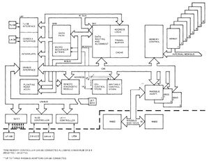
| + | The /750 has a plethora of internal data paths; many of them are contained entirely within the KA750 CPU, and will not be detailed here. The one significant one which connected all the major functional units, including the [[Central Processing Unit|CPU]], [[main memory]], and I/O bus adapters, was the [[CPU/Memory Interconnect]] bus (CMI). The mandatory major CMI sub-systems (and components thereof) were: | ||
| + | |||
| + | * KA750 CPU | ||
| + | ** [[UI750 Unibus Interface]] | ||
** [[FP750 Floating-Point Accelerator]] (optional) | ** [[FP750 Floating-Point Accelerator]] (optional) | ||
* [[MS750 Memory System]] | * [[MS750 Memory System]] | ||
| − | + | ===CMI Options=== | |
| − | + | A variety of optional bus adapters and [[device controller]]s were available for the CMI: | |
| − | + | * [[RH750 Massbus Adapter]] | |
| − | |||
| − | * [[RH750 Massbus Adapter]] | ||
| − | |||
* [[DW750 Second Unibus Interface]] | * [[DW750 Second Unibus Interface]] | ||
| + | * [[CI750 Computer Interconnect Interface]] | ||
* [[DR750 Parallel Interface]] | * [[DR750 Parallel Interface]] | ||
| − | + | ==Physical structure== | |
| + | |||
| + | The VAX-11/750 has one large [[backplane]] ([[DEC part number]] 50-13821/70-16486), into which plug: | ||
| + | |||
| + | * KA750 boards | ||
| + | * CMI option boards (RH750, etc) | ||
| + | * memory array boards | ||
| + | |||
| + | Although it is one physical unit, the backplane can be seen as divided into several logical sections; indeed, the connectors used in the memory array board section are different from those used in the 'main' section of the backplane (where all the other boards between plug in). | ||
| + | |||
| + | However, the biggest difference the sections has to do with which buses are connected to each slot; many slots are thereby customized to a ''particular'' board, which ''has'' to go in that slot - and that slot can't hold ''anything'' else. | ||
| + | |||
| + | The 'main' (i.e. non-memory) section of the backplane can be logically further divided into two sub-sections: one holding optional CMI cards, and another (specifically, slots 1-6 and 10) holding the main memory controller, and the CPU (and optional ancillaries thereof). (Those latter slots have internal buses, such as the MBus and WBus, running between them.) | ||
| + | |||
| + | The CMI appears on the backplane (and nowhere else), and goes to some (but not all) slots/cards. (E.g. the FPA is not a 'CMI' card; it's part of the KA750, and plugs into the /750 backplane which carries the CMI to ''other'' slots, but that's all.) | ||
| − | + | So, one shouldn't put much weight on whether boards plug into the 'main' slots (1-10) on the /750 backplane, because that section holds a mix of special-purpose slots, and 'CMI option' slots (7-9). Although cards that the CMI goes to (MIC, UBI, RDM, WCS) are in some sense 'CMI' cards... because they have dedicated, customized, slots, one should reserve the term 'CMI card' for the cards that can go in the CMI option slots: RH780, etc. | |
| − | |||
| − | |||
| − | |||
| − | |||
| − | |||
| − | |||
| − | |||
| − | |||
| − | |||
| − | |||
| − | |||
| − | |||
| − | |||
| − | |||
| − | |||
| − | ''' | ||
| − | |||
| − | |||
| − | |||
| − | |||
| − | == | + | ===Main backplane configuration=== |
{| class="wikitable" | {| class="wikitable" | ||
| Line 64: | Line 66: | ||
| 4 || L0004 UNIBUS Interface (UBI) | | 4 || L0004 UNIBUS Interface (UBI) | ||
|- | |- | ||
| − | | 5 || L0005 CPU Control Store (CCS) | + | | 5 || L0005 CPU Control Store (CCS)/L008 Patchable Control Store (PCS) |
|- | |- | ||
| 6 || L0006 Remote Diagnostic Module (RDM) | | 6 || L0006 Remote Diagnostic Module (RDM) | ||
| Line 85: | Line 87: | ||
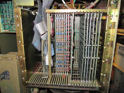
Inside card cage: | Inside card cage: | ||
| − | * Left: [[DD11-D backplane|DD11-DK Unibus | + | * Left: [[DD11-D backplane|DD11-DK Unibus backplane]] (with cards) |
| − | * Center: Memory | + | * Center: Memory backplane section (with cards) |
| − | * Right: | + | * Right: CPU/CMI backplane section (with cards) |
<br clear=all> | <br clear=all> | ||
| Line 93: | Line 95: | ||
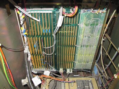
Backplanes: | Backplanes: | ||
| − | * Left: CMI | + | * Left: CPU/CMI backplane section |
| − | * Center: Memory | + | * Center: Memory backplane section |
| − | * Right: DD11-DK - Unibus | + | * Right: DD11-DK - Unibus backplane |
* Lower left corner: 5V and 2.5V Power Supply cables (as thick as a finger!) | * Lower left corner: 5V and 2.5V Power Supply cables (as thick as a finger!) | ||
* Bottom: 5V and 2.5V Power Supplies | * Bottom: 5V and 2.5V Power Supplies | ||
<br clear=all> | <br clear=all> | ||
| − | [[File:VAX-11750_PSUs.JPG| | + | [[File:VAX-11750_PSUs.JPG|300px|thumb|left|VAX-11/750 Power Supply Units]] |
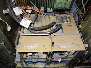
Power Supplies: | Power Supplies: | ||
| Line 107: | Line 109: | ||
<br clear=all> | <br clear=all> | ||
| − | [[File:VAX-11750_Cable_Routing.JPG| | + | [[File:VAX-11750_Cable_Routing.JPG|300px|thumb|left|Cable Routing inside VAX-11/750 (left side open)]] |
Round cables top left: | Round cables top left: | ||
* Console | * Console | ||
| Line 113: | Line 115: | ||
Cables bottom left to top right: | Cables bottom left to top right: | ||
| − | * [[DMF32]] | + | * [[DMF32]] Unibus Multi-Function Communications Interface (3 flat cables) |
* [[TU80K]] [[TU80]] Tape Adapter (2 flat cables, one behind the other) | * [[TU80K]] [[TU80]] Tape Adapter (2 flat cables, one behind the other) | ||
| − | * [[DEUNA]] Ethernet Adapter (round cable) | + | * [[Digital Ethernet UNIBUS Network Adapter|DEUNA]] [[Ethernet]] Adapter (round cable) |
Bottom right: | Bottom right: | ||
| Line 121: | Line 123: | ||
<br clear=all> | <br clear=all> | ||
| − | |||
| − | |||
==See also== | ==See also== | ||
| Line 135: | Line 135: | ||
* [http://www.bitsavers.org/pdf/dec/vax/750/ VAX/750] - documentation at [[Bitsavers]] | * [http://www.bitsavers.org/pdf/dec/vax/750/ VAX/750] - documentation at [[Bitsavers]] | ||
** [http://www.bitsavers.org/pdf/dec/vax/750/MP01377_750_System_Engineering_Drawings_198212.pdf 11/750 Field Maintenance Print Set] (MP01377) | ** [http://www.bitsavers.org/pdf/dec/vax/750/MP01377_750_System_Engineering_Drawings_198212.pdf 11/750 Field Maintenance Print Set] (MP01377) | ||
| − | * [http://vaxarchive.org/hardware/750faq.html Vax 11/750 Frequently Asked Questions] | + | * [http://avitech.com.au/?page_id=1867 VAX 11/750 Parts] - contains many good images |
| + | * [http://vaxarchive.org/hardware/750faq.html Vax 11/750 Frequently Asked Questions] | ||
| + | * [https://en.m.wikiversity.org/wiki/DEC_VAX-11/750_(computer) DEC VAX-11/750] - mostly a copy of the above | ||
* [http://www.datormuseum.se/computers/digital-equipment-corporation/vax-11-750.html VAX-11/750] | * [http://www.datormuseum.se/computers/digital-equipment-corporation/vax-11-750.html VAX-11/750] | ||
* [https://www.cpushack.com/2014/12/08/makings-of-a-comet-the-vax-11750/ Makings of a Comet: The VAX 11/750] | * [https://www.cpushack.com/2014/12/08/makings-of-a-comet-the-vax-11750/ Makings of a Comet: The VAX 11/750] | ||
{{Nav VAX}} | {{Nav VAX}} | ||
Revision as of 23:24, 3 June 2022
| VAX-11/750 | |
 VAX-11/750 | |
| Codename: | Comet |
|---|---|
| Year Introduced: | October 1980 |
| RAM: | Max of 14 MB |
| VUPS: | 0.65 |
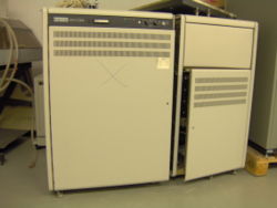
The VAX-11/750 (also known as the VAX/750) is a slower, more compact, but less expensive version of the VAX-11/780. It was primarily implemented in gate array chips holding 400 NAND gates; they were configured at manufacture time into the 39 different types used in the /750.
It is built around the KA750 CPU. It supported several pre-existing DEC I/O buses (UNIBUS and MASSBUS), so there are almost no VAX-11/750-specific peripherals.
It was codenamed 'Comet' by DEC. One of the first OS's available for the 750 was 4.1 BSD. According to 'Quarter Century of UNIX', the DoD could purchase 6 750's for about $150,000 USD.
Contents
Internal structure
The /750 has a plethora of internal data paths; many of them are contained entirely within the KA750 CPU, and will not be detailed here. The one significant one which connected all the major functional units, including the CPU, main memory, and I/O bus adapters, was the CPU/Memory Interconnect bus (CMI). The mandatory major CMI sub-systems (and components thereof) were:
- KA750 CPU
- MS750 Memory System
CMI Options
A variety of optional bus adapters and device controllers were available for the CMI:
- RH750 Massbus Adapter
- DW750 Second Unibus Interface
- CI750 Computer Interconnect Interface
- DR750 Parallel Interface
Physical structure
The VAX-11/750 has one large backplane (DEC part number 50-13821/70-16486), into which plug:
- KA750 boards
- CMI option boards (RH750, etc)
- memory array boards
Although it is one physical unit, the backplane can be seen as divided into several logical sections; indeed, the connectors used in the memory array board section are different from those used in the 'main' section of the backplane (where all the other boards between plug in).
However, the biggest difference the sections has to do with which buses are connected to each slot; many slots are thereby customized to a particular board, which has to go in that slot - and that slot can't hold anything else.
The 'main' (i.e. non-memory) section of the backplane can be logically further divided into two sub-sections: one holding optional CMI cards, and another (specifically, slots 1-6 and 10) holding the main memory controller, and the CPU (and optional ancillaries thereof). (Those latter slots have internal buses, such as the MBus and WBus, running between them.)
The CMI appears on the backplane (and nowhere else), and goes to some (but not all) slots/cards. (E.g. the FPA is not a 'CMI' card; it's part of the KA750, and plugs into the /750 backplane which carries the CMI to other slots, but that's all.)
So, one shouldn't put much weight on whether boards plug into the 'main' slots (1-10) on the /750 backplane, because that section holds a mix of special-purpose slots, and 'CMI option' slots (7-9). Although cards that the CMI goes to (MIC, UBI, RDM, WCS) are in some sense 'CMI' cards... because they have dedicated, customized, slots, one should reserve the term 'CMI card' for the cards that can go in the CMI option slots: RH780, etc.
Main backplane configuration
| Slot | Contents |
|---|---|
| 1 | L0001 Floating-Point Accelerator (FPA) |
| 2 | L0002 Data Path Module (DPM) |
| 3 | L0003 Memory Interconnect (MIC) |
| 4 | L0004 UNIBUS Interface (UBI) |
| 5 | L0005 CPU Control Store (CCS)/L008 Patchable Control Store (PCS) |
| 6 | L0006 Remote Diagnostic Module (RDM) |
| 7 | CMI Option |
| 8 | CMI Option |
| 9 | CMI Option |
| 10 | L0011/L0016/L0022 Memory Controller (MCM) |
VAX-11/750 images
Left of card cage:
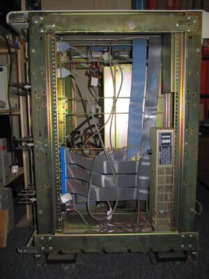
Inside card cage:
- Left: DD11-DK Unibus backplane (with cards)
- Center: Memory backplane section (with cards)
- Right: CPU/CMI backplane section (with cards)
Backplanes:
- Left: CPU/CMI backplane section
- Center: Memory backplane section
- Right: DD11-DK - Unibus backplane
- Lower left corner: 5V and 2.5V Power Supply cables (as thick as a finger!)
- Bottom: 5V and 2.5V Power Supplies
Power Supplies:
- Left: H7104-C 2.5V, 85A max.
- Right: H7104-D 5V, 135A max.
Round cables top left:
- Console
- Remote Diagnose Modem
Cables bottom left to top right:
- DMF32 Unibus Multi-Function Communications Interface (3 flat cables)
- TU80K TU80 Tape Adapter (2 flat cables, one behind the other)
- DEUNA Ethernet Adapter (round cable)
Bottom right:
- H7112 - VAX-11/780 / VAX-11/750 Battery Backup Unit
See also
External links
- VAX Hardware Handbook Volume 1 - the VAX-11/750 is covered in Chapter 4 (pp. 154-171 of the PDF)
- VAX Maintenance Handbook: VAX-11/750 (EK-VAXV3-HB-001)
- VAX/750 - documentation at Bitsavers
- 11/750 Field Maintenance Print Set (MP01377)
- VAX 11/750 Parts - contains many good images
- Vax 11/750 Frequently Asked Questions
- DEC VAX-11/750 - mostly a copy of the above
- VAX-11/750
- Makings of a Comet: The VAX 11/750
| v • d • e VAX Computers and Operating Systems |
|---|
| VAX-11/7xx (including VAX 86x0) - VAX-11/780 • VAX-11/785 • VAX-11/750 • VAX-11/730 • VAX 8600 • VAX 8650
VAX 8000 series (excluding VAX 86x0) - VAX 82xx/83xx series • VAX 85x0/8700/88xx series MicroVAXen (many types also come in VAXserver and VAXstation models) - MicroVAX I • MicroVAX II VAXstation Series - VAXstation I • VAXstation II Late Model VAXen - VAX 4000 series • VAX 6000 series • VAX 7000 series • VAX 9000 series • VAX 10000 series |
| Special Purpose VAXen - VAXft series • rtVAX series • Infoserver series
Clones - CM 1700 • TPA-11/580 |
