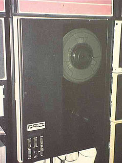
TU10 DECmagtape
| TU10 | |
 TU10 drive | |
| Tape speed: | 45 ips (Forward/Reverse) 150 ips (Rewind) |
|---|---|
| Size: | 19"W x 26"D x 26"H |
| Weight: | 150 lbs |
The TU10 is a classic big tape drive from Digital Equipment Corporation, able to store 5-20 Mytes on a 2400' 0.5" wide tape on a standard 10-1/2" reel. It supports 7-track operation at 200, 556, and 800 BPI, and 9-track at 800 BPI.
The tape transport utilizes a single capstan, with vacuum columns. The drive contains a fair amount of electronics, in the form of FLIP CHIP modules in a 19" wide wirewrap backplane (mounted fore and aft in the drive itself).
It was first used with the PDP-10; to connect to UNIBUS PDP-11's, a TM11 magtape controller is used. The TM11 controller connects to a 'Master' drive, which includes extra modules in the backplane; additional 'Slave' drives (up to seven) may be connected to the Master drive. Details of the controller-Master interface are given here.
Module Inventory
This table shows the number of Flip Chips of each type in the electronics backplane of the Master and Slave TU10's:
| Table | Master | Slave | Function |
|---|---|---|---|
| G050 | 1 | 1 | Dual Gap Head Read Amplifier |
| G060 | 1 | 1 | Mag Tape Compressor, 9-Track |
| G062 | 1 | 1 | Mag Tape Peak Detector, 9-Track |
| G064 | 1 | 1 | Mag Tape Slicer, 9-Track |
| G350 | 1 | 1 | Mag Tape Write Driver |
| G741 | 2 | 2 | Negative Clamp Load |
| G741YA | 1 | 1 | Negative Clamp Load |
| G932 | 1 | 1 | Capstan Servo Pre-Amplifier |
| G933 | 2 | 2 | Reel Motor Amplifier |
| G9340 | 1 | 1 | Brake Logic |
| G9341 | 1 | 1 | Brake Actuator |
| M050 | 1 | 1 | Inverter Driver |
| M100 | 1 | Bus Receiver | |
| M514 | 1 | 1 | TU10 Transceiver |
| M640 | 1 | Bus Driver | |
| M763 | 1 | 1 | 9-Track Write Buffer |
| M765 | 1 | 1 | 9-Track Read Buffer |
| M767 | 1 | 1 | Clock and Skew Delay |
| M7670 | 1 | 1 | Forward BOT Timer |
| M7671 | 1 | Bus Driver | |
| M7672 | 1 | Command Buffer | |
| M7673 | 1 | Data Checker | |
| M768 | 1 | 1 | Delay Selector |
| M769 | 1 | 1 | Function Control |
| M890 | 1 | 1 | Motion Control |
| M891 | 1 | CRC and Write Gating | |
| M892 | 1 | Write and Gap Timing | |
| M895 | 1 | Read Timing | |
| M896 | 1 | CRC Checker | |
| M958 | 1 | Positive Bus Terminatoh | |
| W726 | 1 | 1 | Switch Filter |
Module Locations
This table shows the Flip Chip modules locations in the integral backplane in Master drives:
| Slot | Top | Bottom |
|---|---|---|
| 1 | G933 | |
| 2 | G933 | |
| 3 | G9341 | |
| 4 | G932 | |
| 5 | M908@ | G9340 |
| 6 | M958%% | |
| 7 | M929@ | |
| 8 | M640 | |
| 9 | M891 | |
| 10 | M7673 | |
| 11 | M7672 | |
| 12 | M892 | |
| 13 | M895 | |
| 14 | M7671 | |
| 15 | M100 | M896 |
| 16 | M7670 | |
| 17 | M903@ | G741YA% |
| 18 | M903@ | G741% |
| 19 | M903@ | G741% |
| 20 | M768 | |
| 21 | M514 | |
| 22 | M922@ | M767 |
| 23 | M050 | W726 |
| 24 | M890 | |
| 25 | M769 | |
| 26 | M763 | |
| 27 | G350 | |
| 28 | M765 | |
| 29 | G064 | |
| 30 | G062 | |
| 31 | G060 | |
| 32 | G050 | |
@ = Cable
% = only at end of device bus; M903 cable otherwise
%% = Not required when used with a TM1 control
Slave drives appear to hold a sub-set of this list; slots 6-15 are empty in Slave drives.
Note: In the TU10 Slave backplane drawings, slots 28-30 show different module numbers; however, those original module numbers are crossed out, and the same module numbers as in the Master drive are written in by hand. The captions in those slots (e.g. "Peak Detector"), however, match those of the written-in boards, not the boards originally listed. Thus, the original numbers may be erroneous.