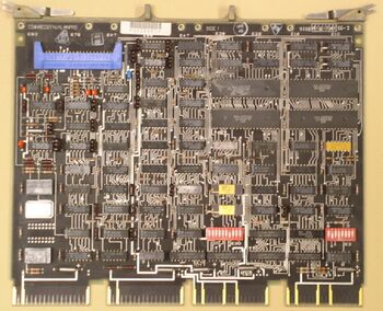
DZV11 asynchronous serial line interface
The DZV11 was a QBUS four port asynchronous serial line mux card for DEC computers; the QBUS equivalent of the UNIBUS DZ11 (with which it is program compatible). Like the original, it used used programmed I/O, and thus could present a considerable load on the CPU when running a high speed line.
A 64-entry FIFO buffer silo was provided on the input side. The DZV11 could operate with full-duplex modems. It provided program-set baud rates (up to 9600 baud), but not split speed. Break could be detected or generated on each line.
Contents
Implementation
Physically, it was a quad card, the M7957; a cable plugged into a 40-pin Berg connector header on the card led the lines out of the computer. The pin assignments in the Berg header are mirrored, so that if the mating Berg connector is plugged in backwards, the only result is to invert the line numbering.
Cabling
Initially, a special BC11U-25 cable was used; it consisted of 4 separate round cables, from a Berg connector, to individual DB25 male connectors (DB-25P) wired as DTEs.
A later alternative to the BC11U consisted of a flat cable from the Berg connector on the card to another on a 4-port distribution panel (DEC part number 70-19964) which held DB-25P male connectors. (The distribution panel may be recognized by the part number on its PCB, 50-15419; the part number for the complete assembly is 54-15420. An earlier version has PCB part number 50-14824, and assembly 54-14825.)
Device registers
| Register | Abbreviation | Address |
|---|---|---|
| Control and Status Register | CSR | 760100 |
| Receiver Buffer Register* | RBUF | 760102 |
| Line Parameter Register* | LPR | 760102 |
| Transmit Control Register | TCR | 760104 |
| Modem Status Register | MSR | 760106 |
| Transmit Data Register | TDR | 760106 |
The RBUF and LPR share an address, as do the MSR and TDR: the RBUF is read only, and the LPR is write only; the MSR is read only, and the TDR is write only. Registers marked with a '*' are word-width only, no byte operations.
The addresses shown are for the first DZ11 in a system (provided that there are no other devices in the floating device address space); additional ones are normally set to be at 760110, 760120, etc.
Control and Status Register (CSR)
| TRDY | TIE | SA | SAE | Unused | Tx Line | RDONE | RIE | MSE | CLR | MAINT | Unused | ||||
| 15 | 14 | 13 | 12 | 11 | 10 | 09 | 08 | 07 | 06 | 05 | 04 | 03 | 02 | 01 | 00 |
- TRDY - Transmitter Ready
- TIE - Transmitter Interrupt Enable
- SA - Silo Alarm
- SAE - Silo Alarm Enable
- Tx Line - Line ready to transmit
- RDONE - Received Done
- RIE - Receiver Interrupt Enable
- MSE - Master Scan Enable
- CLR - Clear input FIFO, CSR and UARTs
- MAINT - Maintenance loopback enabled
Receiver Buffer Register (RBUF)
| DV | OVR | FRERR | PERR | Unused | Rx Line | RBUF | |||||||||
| 15 | 14 | 13 | 12 | 11 | 10 | 09 | 08 | 07 | 06 | 05 | 04 | 03 | 02 | 01 | 00 |
Line Parameter Register (LPR)
| Unused | RXON | Speed | ODDP | PAREN | STOP | CLEN | Unused | Line | |||||||
| 15 | 14 | 13 | 12 | 11 | 10 | 09 | 08 | 07 | 06 | 05 | 04 | 03 | 02 | 01 | 00 |
Transmit Control Register (TCR)
| Unused | DTR | Unused | Line Enabled | ||||||||||||
| 15 | 14 | 13 | 12 | 11 | 10 | 09 | 08 | 07 | 06 | 05 | 04 | 03 | 02 | 01 | 00 |
Modem Status Register (MSR)
| Unused | CD | Unused | RI | ||||||||||||
| 15 | 14 | 13 | 12 | 11 | 10 | 09 | 08 | 07 | 06 | 05 | 04 | 03 | 02 | 01 | 00 |
Transmit Data Register (TDR)
| Unused | Break | TBUF | |||||||||||||
| 15 | 14 | 13 | 12 | 11 | 10 | 09 | 08 | 07 | 06 | 05 | 04 | 03 | 02 | 01 | 00 |
Details information
The DZV11 uses the DEC LSI-11 Bus interface chips; the DZV11 technical manual (below) includes detailed descriptions of all of them in Appendix A, 'IC Descriptions' - along with a detailed description of the UART chip, used across essentially all DEC asynchronous serial line cards of this generation.
External links
- DZV11 asynchronous multiplexer user's guide (EK-DZV11-UG-002)
- DZV11 asynchronous multiplexer technical manual (EK-DZV11-TM-001)
- DZV11 Field Maintenance Print Set (MP-00462)
