Difference between revisions of "PDP-10 memories"
m (correct conn nm) |
m (Avoid redir) |
||
| Line 3: | Line 3: | ||
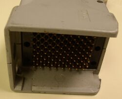
[[Image:KBusQCUnlatched.jpg|250px|thumb|left|KI-type memory bus Quick Latch connector (in unlatched position)]] | [[Image:KBusQCUnlatched.jpg|250px|thumb|left|KI-type memory bus Quick Latch connector (in unlatched position)]] | ||
| − | There were three generations of [[main memory]] [[bus]] (which ran sequentially through memory units to a [[terminator]]), and memory units to them. The first two were the so-called 'external memory bus', in KA (18-bit [[address]]) and KI (22-bit) forms (for the [[KA10]], and [[KI10]] and early [[KL10]], respectively), although they also had [[protocol]] differences. The last was the 'internal memory bus', the 'S-Bus'. (For the later KL10s, a later version of the S-Bus, the X-Bus, differed only in the [[logic family]] it interfaced to.) The differences between the two external bus types required a [[KI10-M Memory Bus Adapter]] if KA-bit units were to be attached to a KI10. Similarly, KI-type units could be attached to the S-Bus using a [[DMA20 Memory Bus | + | There were three generations of [[main memory]] [[bus]] (which ran sequentially through memory units to a [[terminator]]), and memory units to them. The first two were the so-called 'external memory bus', in KA (18-bit [[address]]) and KI (22-bit) forms (for the [[KA10]], and [[KI10]] and early [[KL10]], respectively), although they also had [[protocol]] differences. The last was the 'internal memory bus', the 'S-Bus'. (For the later KL10s, a later version of the S-Bus, the X-Bus, differed only in the [[logic family]] it interfaced to.) The differences between the two external bus types required a [[KI10-M Memory Bus Adapter]] if KA-bit units were to be attached to a KI10. Similarly, KI-type units could be attached to the S-Bus using a [[DMA20 Memory Bus Adapter]]. |
The S-Bus (and the later version, the X-Bus, used with MOS 'internal' memory) performs memory transfers in blocks of up to four [[word]]s, so that four words can be read in any cycle; the block can start with any word within the block. The KL10 contains a pair of S-Busses, designated 0 and 1. | The S-Bus (and the later version, the X-Bus, used with MOS 'internal' memory) performs memory transfers in blocks of up to four [[word]]s, so that four words can be read in any cycle; the block can start with any word within the block. The KL10 contains a pair of S-Busses, designated 0 and 1. | ||
Revision as of 13:21, 13 October 2021
PDP-10 memories were generally all multi-port memory units. The PDP-10 CPU used one port (one per CPU in multi-processor systems); the others are used by channels for mass storage, such as disks. Interleaving was generally supported between units; usually in pairs, or sometimes groups of four. All except the very last ones were core, and supported parity for error detection; the others were MOS DRAM, and used ECC to protect the memory contents.
There were three generations of main memory bus (which ran sequentially through memory units to a terminator), and memory units to them. The first two were the so-called 'external memory bus', in KA (18-bit address) and KI (22-bit) forms (for the KA10, and KI10 and early KL10, respectively), although they also had protocol differences. The last was the 'internal memory bus', the 'S-Bus'. (For the later KL10s, a later version of the S-Bus, the X-Bus, differed only in the logic family it interfaced to.) The differences between the two external bus types required a KI10-M Memory Bus Adapter if KA-bit units were to be attached to a KI10. Similarly, KI-type units could be attached to the S-Bus using a DMA20 Memory Bus Adapter.
The S-Bus (and the later version, the X-Bus, used with MOS 'internal' memory) performs memory transfers in blocks of up to four words, so that four words can be read in any cycle; the block can start with any word within the block. The KL10 contains a pair of S-Busses, designated 0 and 1.
Most the memory units had a configuration panel which allowed ports to be enabled, and set the memory's address (often independently for each port); similarly, some level of interleaving could be set.
Memory systems
18-bit external:
22-bit external:
Internal:
The first two groups are all multi-port (generally 4 ports per memory system in the first group, and 8 in the second). The last group were for the later final KL10s (models KL10-E and KL10-R). All except the MF20 and MG20 were core.
