Difference between revisions of "HSD10 DSSI-to-SCSI Bus Adapter"
m (→External links: Links corrected) |
m (New category) |
||
| Line 85: | Line 85: | ||
* [https://www.zx.net.nz/mirror/h18000.www1.hp.com/info/SP6126/SP6126PF.PDF HSD10 Array Controller Operating Software Version 1.0 Software Product Description] (AE-QW8WA-TE) | * [https://www.zx.net.nz/mirror/h18000.www1.hp.com/info/SP6126/SP6126PF.PDF HSD10 Array Controller Operating Software Version 1.0 Software Product Description] (AE-QW8WA-TE) | ||
| − | [[Category:DEC Mass Storage]] | + | [[Category: DEC Mass Storage]] |
| − | [[Category:DSSI]] | + | [[Category: DSSI]] |
| − | [[Category: | + | [[Category: DSSI Hierarchical Storage Controllers]] |
| − | [[Category: | + | [[Category: SCSI]] |
Revision as of 22:00, 12 January 2024

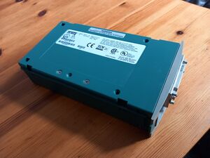
The HSD10 is a DSSI-to-SCSI bus adapter respctively an SCSI array controller. It connects up to seven SCSI devices (disk and tape drives) to a DSSI bus as a single DSSI node, thus allowing the flexibility to expand the amount of DSSI-connected storage devices or to free up DSSI nodes for host connections. The attached SCSI devices are transparently mapped to DSSI devices, either as individual devices, parts of individual devices (called "partitions"), as stripe sets (RAID 0) or (depending on firmware) as mirror sets (RAID 1).
Contents
Description

The HSD10 array controller is housed in a 3.5-inch StorageWorks form factor Storage Building Block (SBB); it mounts in a BA350-SA shelf, or a BA350-KA StorageWorks Deskside Expansion Unit, along with up to six SCSI devices. The StorageWorks shelves may be mounted in the SW500 or SW800 StorageWorks cabinets.
Two HSD10 array controllers may be used in conjunction with separate DSSI buses to provide device access with no single points-of-failure in the access path.
The optional inclusion of 16 or 32MB of read cache can reduce response time substantially.
The HSD10 provides utilities for:
- Formatting
- Qualifying
- Exercising
- Mapping
of the attached SCSI devices.
The HSD10 is a member of the HSx Family of Hierachical Storage Controllers.
The HSD10 is the enhanced successor model of the HSD05; there are also two newer and more powerful models, the HSD30 and the HSD50.
Features
- Direct connection to the DSSI Bus
- Provides controller based Raid 0 (striping)
- Multihost operation; up to four hosts on the DSSI bus
- Up to 1000 I/O requests per second and 3.0 MB/second
- Attached disks can be warm-swapped
- Up to 32MB of read cache
- Connection to a VCS console via RS communications port
- SCSI wide drive support (controller operates in 8-bit mode)
HSD10 Controller Firmware
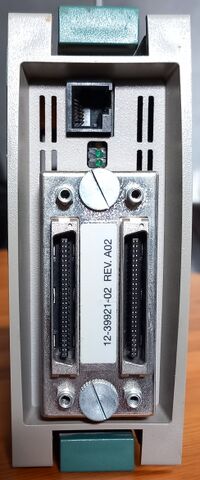
HSD10 firmware resides in a flash electrically erasable programmable read-only memory (EEPROM) device that can accept firmware upgrades via the front panel modular jack connector. Through an on-board firmware command utility, you can set device parameters including node name, system ID, disk and tape allocation classes, and performance optimization parameters. It also can be used for device formatting and qualification and to access device information.
Setting Parameters on the HSD10 Array Controller
The VMS Diagnostic and Utility Protocol (DUP) utility and the 6-pin serial communications port on the front panel provide a gateway to modifying HSD10 array controller parameters. The front panel communications port can be used for connection to a VCS (Virtual Console System) console. Parameter settings can be made this way if desired. You can run the DUP utility from either the system console or from the VMS system prompt. Once a connection to the HSD10 array controller command utility is established, it is used to set and show HSD10 parameters.
Accessing the HSD10 from the VAX console prompt
One DSSI bus:
>>> SET HOST/DUP/DSSI <nodenumber> <task>
Two DSSI buses:
>>> SET HOST/DUP/DSSI/BUS:<busnumber> <nodenumber> <task>
Accessing the HSD10 from VMS DCL
$! Load Driver
$  MC SYSGEN CONNECT FYA0/NOADAPTER
$!
$! Connect
$  SET HOST /DUP /SERVER=MSCPSDUP /TASK=<taskname> <nodename> /LOG
$! <taskname> = PARAMS or = DIRECT
RAID 1 Setup - Creating / Rebuilding / Removing Mirrorsets
CREATE MIRRORSET M<x>
ADD MIRRORSET M<x> D<xxx> D<yyy> [D<zzz>]
SET MIRRORSET M<x> /NEW
MAP UNIT M<x> DIA<yy> [/PARTITION=<number>]
REBUILD MIRRORSET M<x> D<xxx> [D<zzz>]
DELETE UNIT DIA<yy> (= UNMAP)
REMOVE MIRRORSET M<x> D<xxx> [D<yyy>] [D<zzz>]
DELETE MIRRORSET M<x>
Units = devices mapped towards computer
Disks = physical disks
Devices = both units and disks
D1<id>00 = Disk <id>
M = Mirrorset
S = Stripeset