Difference between revisions of "DEC Ethernet Transceivers"
(Separated from "Ethernet Transceivers" into DEC specific page & "Removable Tap Assembly Instructions" added (partly)) |
(Finished "Removable Tap Assembly Instructions") |
||
| Line 95: | Line 95: | ||
# Slide clamp assembly onto tap body. | # Slide clamp assembly onto tap body. | ||
# Install clamp screw and tighten with hex wrench. | # Install clamp screw and tighten with hex wrench. | ||
| + | |||
| + | <br clear=all> | ||
| + | |||
| + | ===Removing Tap Assembly Dust Cover=== | ||
| + | |||
| + | [[File:Tap_05.png|400px|thumb|left|Removing Tap Assembly Dust Cover]] | ||
| + | |||
| + | Pull dust cover off tap assembly. | ||
| + | |||
| + | '''Caution:'''<br> | ||
| + | '''Pins inside the tap body are easily bent.''' | ||
| + | |||
| + | <br clear=all> | ||
| + | |||
| + | ===Drilling Through Coaxial Cable to Center Conductor=== | ||
| + | |||
| + | [[File:Tap_06.png|400px|thumb|left|Drilling Through Coaxial Cable to Center Conductor]] | ||
| + | |||
| + | Steps: | ||
| + | # Position tap assembly for drilling. | ||
| + | # Using drill end of installation tool, insert tool into probe hole in tap assembly and rotate tool clockwise, drilling through cable to center conductor. | ||
| + | |||
| + | '''Note:'''<br> | ||
| + | '''The drill must bottom on the tap body.''' | ||
| + | |||
| + | <br clear=all> | ||
| + | |||
| + | ===Inserting Probe Assembly into Tap/Cable Assembly=== | ||
| + | |||
| + | [[File:Tap_07.png|400px|thumb|left|Inserting Probe Assembly into Tap/Cable Assembly]] | ||
| + | |||
| + | Steps: | ||
| + | # Remove any shield particles from hole in cable. | ||
| + | # Using wrench end of installation tool, thread probe assembly into tap assembly until probe assembly bottoms. | ||
| + | |||
| + | <br clear=all> | ||
| + | |||
| + | ===Connecting Tap/Cable Assembly to Transceiver=== | ||
| + | |||
| + | [[File:Tap_08.png|400px|thumb|left|Connecting Tap/Cable Assembly to Transceiver]] | ||
| + | |||
| + | Steps: | ||
| + | # Remove push-pins from turret. | ||
| + | # Align tap braid and probe posts with the contacts on the transceiver, and insert tap/cable assembly into turret on transceiver carefully. | ||
| + | # Install two push-pins (P/N 74-32789-01) into turret and through tap until they bottom on the turret. | ||
| + | |||
| + | '''Note'''<br> | ||
| + | '''The transceiver may be rotated so that the transceiver cable can be connected at the opposite end.''' | ||
<br clear=all> | <br clear=all> | ||
Revision as of 16:31, 10 June 2022
Contents
- 1 DEC Ethernet Transceiver Models
- 2 Removable Tap Assembly Instructions
- 2.1 Tap Installation Tools
- 2.2 Tap Assembly
- 2.3 Preparing Tap Body
- 2.4 Positioning Coaxial Cable and Assembling Tap
- 2.5 Removing Tap Assembly Dust Cover
- 2.6 Drilling Through Coaxial Cable to Center Conductor
- 2.7 Inserting Probe Assembly into Tap/Cable Assembly
- 2.8 Connecting Tap/Cable Assembly to Transceiver
DEC Ethernet Transceiver Models
H4000 Ethernet Transceiver (Thickwire)
Year of introduction: 1982
You cannot disable the Heartbeat feature of the standard H4000 Ethernet Transceiver, there is a special version (H4000-BA) without Heartbeat available in case you need that.
H4000 with Inclusive Tap
The H4000 Ethernet Transceiver with Inclusive Tap was the very first Ethernet Transceiver from DEC.
It has got two drawbacks:
- If the tap pin gets damaged, the whole unit is inoperable and cannot be repaired.
- It is very inconvenient to mount the unit to a Thickwire segment difficult to access, e.g. located in a ceiling plenum.
H4000 with Removable Tap
The H4000 Ethernet Transceiver with Removable Tap is an improved version of the model with a fixed tap.
You can tap the cable using the removable tapping unit (which is much smaller and lighter than the complete unit) and attach the rest of the unit when the tapping is done.
If the tap gets damaged, you can use a replacement one.
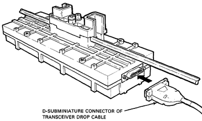
<Picture of an H4000 with Removable Tap>
H4005 Ethernet Transceiver (Thickwire)
Year of introduction: 1988?
<Picture of an H4005>
DESTA Thinwire Ethernet Station Adapter
Year of introduction: 1986
Early DESTA
The early DESTA (REV A) is a H4005 with a modified top assembly carrying a female BNC socket.
You can replace the BNC top assembly with that of an H4005 and thus use the early DESTA with Thickwire Ethernet.
On the other hand you can use the top assembly of an early DESTA to use an H4005 for Thinwire Ethernet.
<Picture of an early DESTA>
Late DESTA
The late DESTA (REV B) is housed in a slightly smaller box and the BNC socket is fixed.
<Picture of a late DESTA>
H3350 Twisted Pair Transceiver
Year of introduction: ?
<Picture of an H3350 Twisted Pair Transceiver>
DECXM Thinwire Transceiver
Year of introduction: ?
<Picture of a DECXM Thinwire Transceiver>
DETPM 10BaseT Transceiver
Year of introduction: ?
<Picture of a DETPM 10BaseT Transceiver>
Removable Tap Assembly Instructions
from: EK-H4005-IN-002 H4005 DIGITAL Ethernet Transceiver With Removable Tap Assembly Installation Card
Tap Installation Tools
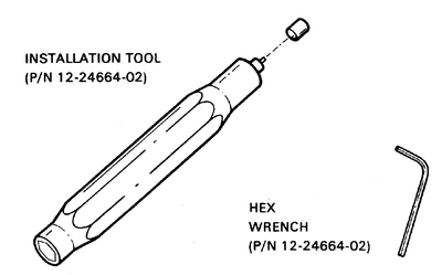
Not included in tools set; typically good for 10-15 installations
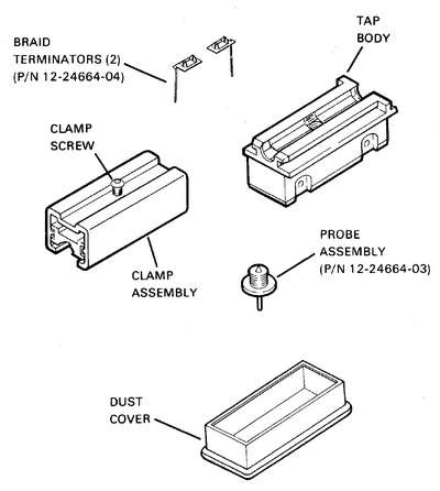
Tap Assembly
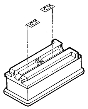
Preparing Tap Body
Install braid terminators into tap body.
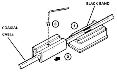
Positioning Coaxial Cable and Assembling Tap
Steps:
- Position tap body on black band that is on coaxial cable.
- Slide clamp assembly onto tap body.
- Install clamp screw and tighten with hex wrench.
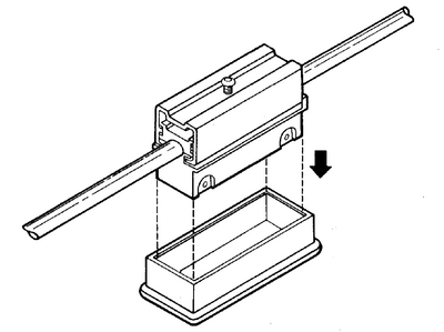
Removing Tap Assembly Dust Cover
Pull dust cover off tap assembly.
Caution:
Pins inside the tap body are easily bent.
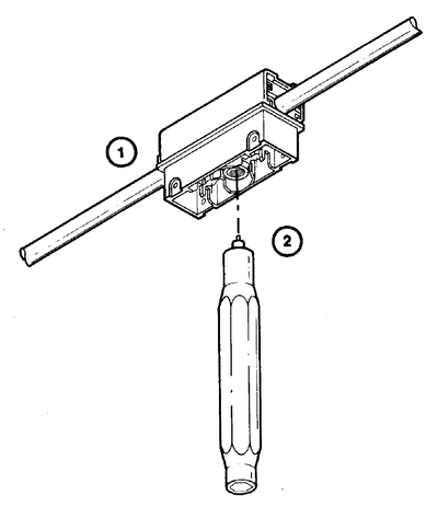
Drilling Through Coaxial Cable to Center Conductor
Steps:
- Position tap assembly for drilling.
- Using drill end of installation tool, insert tool into probe hole in tap assembly and rotate tool clockwise, drilling through cable to center conductor.
Note:
The drill must bottom on the tap body.
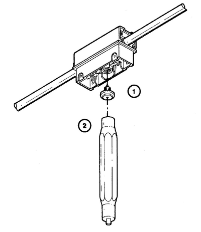
Inserting Probe Assembly into Tap/Cable Assembly
Steps:
- Remove any shield particles from hole in cable.
- Using wrench end of installation tool, thread probe assembly into tap assembly until probe assembly bottoms.
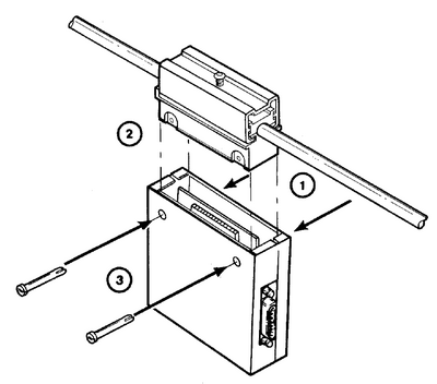
Connecting Tap/Cable Assembly to Transceiver
Steps:
- Remove push-pins from turret.
- Align tap braid and probe posts with the contacts on the transceiver, and insert tap/cable assembly into turret on transceiver carefully.
- Install two push-pins (P/N 74-32789-01) into turret and through tap until they bottom on the turret.
Note
The transceiver may be rotated so that the transceiver cable can be connected at the opposite end.
