Difference between revisions of "M7850 parity controller"
(+ detail, img) |
m (→See also: +M7259 Parity Control Module) |
||
| Line 21: | Line 21: | ||
==See also== | ==See also== | ||
| + | * [[M7259 Parity Control Module]] | ||
* [[UNIBUS parity]] | * [[UNIBUS parity]] | ||
Revision as of 20:19, 6 July 2022
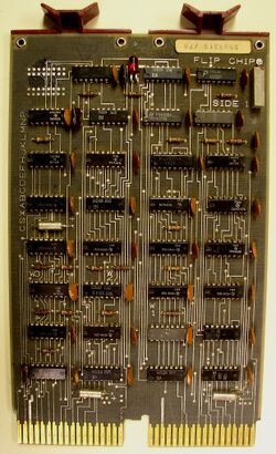
The M7850 parity controller is an optional accessory for mid-period main memory on the UNIBUS; it provides byte parity for memory units (such as the MM11-D core memory and MS11 32KB MOS memory) which i) provide the two extra bits of memory per PDP-11 word needed to hold the parity, and ii) are set up to interact with the M7850. It works with both core memory and MOS DRAM memory.
Memory access time on read is increased by 150 nsec if there is no error, and by 200 nsec if there is; cycle time on write is increased by 40 nsec. If an error occurs, an LED on the M7850 is illuminated.
Unlike the earlier M7259 Parity Control Module, which has different backplane wiring for parity and non-parity memory, no hardware changes are needed to switch from non-parity to parity memory with the M7850. When the M7850 is inserted in a backplane which also holds parity-capable (as above) memory, the latter detects the presence of the M7850 and alters its operation to function with the M7850 to provide parity checking.
The M7850 is a dual format card, which plus into the two top (AB) sections of the MUD backplane into which the associated memory unit(s) are plugged. (Since all the relevant memory modules are hex-sized, the M7850 must go in another slot.) One M7850 can provide parity support to as many memory units as the backplane holds.
Control and Status Register
The M7850 has a single register to control and monitor its operation. Its address may be set in the range 0772100-0772136 by a group of jumpers on the M7850. Its format is:
| ParErr | Unused | ErrAddr | Unused | WrWrong | Unused | SignalErr | |||||||||
| 15 | 14 | 13 | 12 | 11 | 10 | 09 | 08 | 07 | 06 | 05 | 04 | 03 | 02 | 01 | 00 |
Errors are not signaled to the CPU unless bit 0 is set. After an error, the ErrAddr field contains the highest-order address bits (A17-A11) of the location which produced the error. Bits 0 and 2 can be written by the CPU; they and bit 15 are cleared by the INIT bus signal.
See also
External links
- M7850 parity controller maintenance manual (EK-M7850-MM-001)
- 11/34 Vol. 2 Field Maintenance Print Set - the M7850 is covered on pp. 93-95 of the PDF
