Difference between revisions of "KE11-E Extended Instruction Set"
(A decent start) |
m (Better cat) |
||
| (4 intermediate revisions by the same user not shown) | |||
| Line 1: | Line 1: | ||
| + | [[Image:M7238KE11-EEIS.jpg|350px|thumb|right|M7238 card]] | ||
| + | |||
The '''KE11-E Extended Instruction Set''' is the optional [[PDP-11 Extended Instruction Set]] for the [[KD11-A CPU]] of the [[PDP-11/40]]; it implements multiply, divide, and multi-bit shift instructions. It is also used by the [[KE11-F Floating Instruction Set]] option. | The '''KE11-E Extended Instruction Set''' is the optional [[PDP-11 Extended Instruction Set]] for the [[KD11-A CPU]] of the [[PDP-11/40]]; it implements multiply, divide, and multi-bit shift instructions. It is also used by the [[KE11-F Floating Instruction Set]] option. | ||
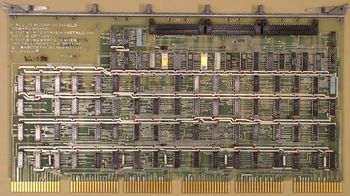
| − | Physically, it consists of a single [[DEC card form factor|hex]] board, the M7238, which plugs into a pre-wired slot in the [[Central Processing Unit|CPU]] [[backplane]], and also connects up to the basic CPU through three [[over the back]] 40-[[conductor]] [[flat cable]]s. | + | Physically, it consists of a single [[DEC card form factor|hex]] board, the M7238, which plugs into a pre-wired slot in the [[Central Processing Unit|CPU]] [[backplane]], and also connects up to the basic CPU's [[microcode]] [[bus]] through three [[over the back]] BC08-R 40-[[conductor]] [[flat cable]]s which plug into [[Berg connector]]s on the M7232 μWord card of the KD11-A. |
| + | |||
| + | The KE11-E includes its own microcode [[Read-only memory|ROM]], which produces an additional 24 bits width of microcode (to control the [[data path]]s and [[register]]s on the M7238), but also provides 44 bits of microcode to control registers and datapaths in the basic CPU. (The CPU's microcode is 56 bits wide; the other 12 bits are unused by the KE11-E, and are sent as 0's to the CPU.) | ||
| − | + | ==External links== | |
| − | + | * [http://www.bitsavers.org/pdf/dec/pdp11/1140/KE11_RefMan.pdf KE11-E and KE11-F instruction set options user's manual] (EK-KE11E-OP-001) <!-- also http://www.bitsavers.org/www.computer.museum.uq.edu.au/pdf/EK-KE11E-OP-001%20KE11-E%20and%20KE11-F%20Instruction%20Set%20Options%20User's%20Manual.pdf --> | |
| + | * [http://www.bitsavers.org/www.computer.museum.uq.edu.au/pdf/EK-KE11E-TM-002%20KE11-E%20and%20KE11-F%20Instruction%20Set%20Options%20Manual.pdf KE11-E and KE11-F instruction set options manual] (EK-KE11E-TM-002) | ||
| + | * [http://www.bitsavers.org/pdf/dec/pdp11/1140/KE11-E_Engineering_Drawings.pdf KE11-E extended instruction set (EIS) option engineering drawings] <!-- also https://manx-docs.org/collections/hcps/KE11-EIS.pdf --> | ||
| − | + | [[Category: PDP-11 UNIBUS Processors]] | |
Latest revision as of 00:33, 12 October 2022
The KE11-E Extended Instruction Set is the optional PDP-11 Extended Instruction Set for the KD11-A CPU of the PDP-11/40; it implements multiply, divide, and multi-bit shift instructions. It is also used by the KE11-F Floating Instruction Set option.
Physically, it consists of a single hex board, the M7238, which plugs into a pre-wired slot in the CPU backplane, and also connects up to the basic CPU's microcode bus through three over the back BC08-R 40-conductor flat cables which plug into Berg connectors on the M7232 μWord card of the KD11-A.
The KE11-E includes its own microcode ROM, which produces an additional 24 bits width of microcode (to control the data paths and registers on the M7238), but also provides 44 bits of microcode to control registers and datapaths in the basic CPU. (The CPU's microcode is 56 bits wide; the other 12 bits are unused by the KE11-E, and are sent as 0's to the CPU.)
