Difference between revisions of "TU56 DECtape Transport"
(Add a few bits) |
m (→External links: +Henk page) |
||
| (11 intermediate revisions by the same user not shown) | |||
| Line 3: | Line 3: | ||
| manufacturer = [[Digital Equipment Corporation]] | | manufacturer = [[Digital Equipment Corporation]] | ||
| media = [[DECTape]] | | media = [[DECTape]] | ||
| − | | controller = [[ | + | | controller = [[TC08 DECtape Controller|TC08]], [[TD8-E Simple DECtape Control|TD8-E]], [[TC11 DECtape controller|TC11]] |
| image = Tu56.jpg | | image = Tu56.jpg | ||
| caption = A TU56 drive | | caption = A TU56 drive | ||
|}} | |}} | ||
| − | + | The '''TU56 DECtape Transport''' is an enhanced successor to the [[TU55 DECtape Transport|TU55]] [[DECtape]] [[magnetic tape drive]]. The usual configuration was dual-drive (referred to as 'dual transport'), but a single-drive version, the '''TU56H''', was available. The '''TU56M''' (dual) and '''TU56HM''' (single) model included 5 G888 Read/Write Amplifier [[FLIP CHIP]]s, for use with [[device controller]]s which do not include that functionality. | |
| − | [[Category:Tape Drives]] | + | ==Card locations and counts== |
| + | |||
| + | The TU56 contains a small [[backplane]] holding a number of [[FLIP CHIP]] modules. The module location chart for the TU56 backplane is (starting at the right-hand side, viewed from the board-insertion side): | ||
| + | |||
| + | {| class="wikitable" | ||
| + | ! Slot !! A !! B !! Use | ||
| + | |- | ||
| + | | 1 || colspan="2" style="text-align:center;" | G848 || Left forward | ||
| + | |- | ||
| + | | 2 || colspan="2" style="text-align:center;" | G848 || Left reverse | ||
| + | |- | ||
| + | | 3 || G859 || G847 | ||
| + | |- | ||
| + | | 4 || M941 || M922% | ||
| + | |- | ||
| + | | 5 || M531 || M113 | ||
| + | |- | ||
| + | | 6 || M908 || M113 | ||
| + | |- | ||
| + | | 7 || M908 || M117 | ||
| + | |- | ||
| + | | 8 || M040 || M302 | ||
| + | |- | ||
| + | | 9 || colspan="2" style="text-align:center;" | G851% | ||
| + | |- | ||
| + | | 10 || colspan="2" style="text-align:center;" | W032# | ||
| + | |- | ||
| + | | 11 || colspan="2" style="text-align:center;" | W032# | ||
| + | |- | ||
| + | | 12 || colspan="2" style="text-align:center;" | G851% | ||
| + | |- | ||
| + | | 13 || G888* || G888* | ||
| + | |- | ||
| + | | 14 || G888* || G888* | ||
| + | |- | ||
| + | | 15 || M040 || G888* | ||
| + | |- | ||
| + | | 16 || M117 || M113 | ||
| + | |- | ||
| + | | 17 || || M922% | ||
| + | |- | ||
| + | | 18 || M941 || G847 | ||
| + | |- | ||
| + | | 19 || colspan="2" style="text-align:center;" | G848 || Right forward | ||
| + | |- | ||
| + | | 20 || colspan="2" style="text-align:center;" | G848 || Right reverse | ||
| + | |} | ||
| + | |||
| + | (% = Connector)<br> | ||
| + | (# = TU56H only)<br> | ||
| + | (* = Optional, not used in standard controllers) | ||
| + | |||
| + | ===Module counts=== | ||
| + | |||
| + | Module counts (drawn from the module count chart, mostly confirmed in the module utilization drawing): | ||
| + | |||
| + | [[Image:TU56Boards.jpg|thumb|right|400px|Internals of a TU56 drive]] | ||
| + | |||
| + | {| class="wikitable" | ||
| + | ! Count !! Type !! Description | ||
| + | |- | ||
| + | | 1 || G742# || Positive Logic Jumper Card | ||
| + | |- | ||
| + | | 2& || G847 || Dual Motor Voltage Control | ||
| + | |- | ||
| + | | 4& || G848 || Motor Control | ||
| + | |- | ||
| + | | 2& || G851 || Relay | ||
| + | |- | ||
| + | | 1 || G859 || Clock Regulator | ||
| + | |- | ||
| + | | 5 || G888* || Manchester Reader/Writer (Read/Write Amplifier) | ||
| + | |- | ||
| + | | 2& || M040 || Solenoid Driver | ||
| + | |- | ||
| + | | 3& || M113 || 10x2 Input NAND Gate | ||
| + | |- | ||
| + | | 2& || M117 || 6x4 Input NAND Gate | ||
| + | |- | ||
| + | | 1 || M302 || Dual Delay MV | ||
| + | |- | ||
| + | | 1 || M531# || Bus Converter | ||
| + | |- | ||
| + | | 2 || M908 || Connector | ||
| + | |- | ||
| + | | 2& || M922 || Cable Connector | ||
| + | |- | ||
| + | | 1 || M923* || Cable Connector | ||
| + | |- | ||
| + | | 2& || M941% || Jumper Card | ||
| + | |- | ||
| + | | 2 || W032 || Cable Connector | ||
| + | |} | ||
| + | |||
| + | (& = dual drive; half this in a single drive)<br> | ||
| + | (# = M531 is used with a negative logic controller; G742 with a positive logic controller)<br> | ||
| + | (% = Replaced with a W5l3 when the transport is connected to a relay driver controller)<br> | ||
| + | (* = Optional, not used in standard controllers) | ||
| + | |||
| + | ==See also== | ||
| + | |||
| + | * [[TU55 DECtape Transport]] | ||
| + | |||
| + | ==External links== | ||
| + | |||
| + | * [http://www.bitsavers.org/pdf/dec/dectape/tu56/DEC-00-HRTC-D_TU56_Mantenance_Manual_Jan73.pdf TU56 DECtape Transport Maintenance Manual] (DEC-00-HRTC-D) | ||
| + | * [http://www.bitsavers.org/pdf/dec/dectape/tu56/DEC-TU56-IPB-2_TU56_IPB_1973.pdf TU56 DECtape Illustrated Parts Breakdown] (DEC-TU56-IPB-2) | ||
| + | * [http://www.bitsavers.org/pdf/dec/dectape/tu56/TU56_Rev_AN_Engineering_Drawings_Apr73.pdf TU56 DECtape transport engineering drawings] (TU56-77-AN) | ||
| + | * [http://www.bitsavers.org/pdf/dec/dectape/tu56/TU56H_Engineering_Drws_Jun73.pdf TU56 DECtape transport engineering drawings] (TU56-78-AP) | ||
| + | * [http://www.bitsavers.org/pdf/dec/dectape/tu56/TU56_Rev_AV_Engineering_Drawings_Oct74.pdf TU56 DECtape transport engineering drawings] (TU56-83-AV) | ||
| + | * [https://www.pdp-11.nl/peripherals/tape/tu56-info.html TU56 tape drive] | ||
| + | |||
| + | [[Category: DEC Tape Drives]] | ||
| + | [[Category: DECtape]] | ||
Latest revision as of 23:31, 28 February 2023
| TU56 | |
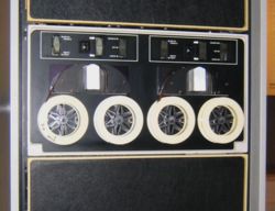
 A TU56 drive | |
| Manufacturer: | Digital Equipment Corporation |
|---|---|
| Drive Controller(s): | TC08, TD8-E, TC11 |
| Media: | DECTape |
The TU56 DECtape Transport is an enhanced successor to the TU55 DECtape magnetic tape drive. The usual configuration was dual-drive (referred to as 'dual transport'), but a single-drive version, the TU56H, was available. The TU56M (dual) and TU56HM (single) model included 5 G888 Read/Write Amplifier FLIP CHIPs, for use with device controllers which do not include that functionality.
Card locations and counts
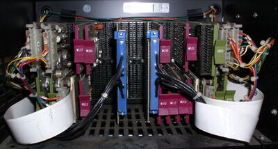
The TU56 contains a small backplane holding a number of FLIP CHIP modules. The module location chart for the TU56 backplane is (starting at the right-hand side, viewed from the board-insertion side):
| Slot | A | B | Use |
|---|---|---|---|
| 1 | G848 | Left forward | |
| 2 | G848 | Left reverse | |
| 3 | G859 | G847 | |
| 4 | M941 | M922% | |
| 5 | M531 | M113 | |
| 6 | M908 | M113 | |
| 7 | M908 | M117 | |
| 8 | M040 | M302 | |
| 9 | G851% | ||
| 10 | W032# | ||
| 11 | W032# | ||
| 12 | G851% | ||
| 13 | G888* | G888* | |
| 14 | G888* | G888* | |
| 15 | M040 | G888* | |
| 16 | M117 | M113 | |
| 17 | M922% | ||
| 18 | M941 | G847 | |
| 19 | G848 | Right forward | |
| 20 | G848 | Right reverse | |
(% = Connector)
(# = TU56H only)
(* = Optional, not used in standard controllers)
Module counts
Module counts (drawn from the module count chart, mostly confirmed in the module utilization drawing):
| Count | Type | Description |
|---|---|---|
| 1 | G742# | Positive Logic Jumper Card |
| 2& | G847 | Dual Motor Voltage Control |
| 4& | G848 | Motor Control |
| 2& | G851 | Relay |
| 1 | G859 | Clock Regulator |
| 5 | G888* | Manchester Reader/Writer (Read/Write Amplifier) |
| 2& | M040 | Solenoid Driver |
| 3& | M113 | 10x2 Input NAND Gate |
| 2& | M117 | 6x4 Input NAND Gate |
| 1 | M302 | Dual Delay MV |
| 1 | M531# | Bus Converter |
| 2 | M908 | Connector |
| 2& | M922 | Cable Connector |
| 1 | M923* | Cable Connector |
| 2& | M941% | Jumper Card |
| 2 | W032 | Cable Connector |
(& = dual drive; half this in a single drive)
(# = M531 is used with a negative logic controller; G742 with a positive logic controller)
(% = Replaced with a W5l3 when the transport is connected to a relay driver controller)
(* = Optional, not used in standard controllers)
See also
External links
- TU56 DECtape Transport Maintenance Manual (DEC-00-HRTC-D)
- TU56 DECtape Illustrated Parts Breakdown (DEC-TU56-IPB-2)
- TU56 DECtape transport engineering drawings (TU56-77-AN)
- TU56 DECtape transport engineering drawings (TU56-78-AP)
- TU56 DECtape transport engineering drawings (TU56-83-AV)
- TU56 tape drive
