Difference between revisions of "MXV11-A Multifunction Option Module"
From Computer History Wiki
(An OK start) |
m (→Further reading: +MXV11 Bootstrap Problems) |
||
| (10 intermediate revisions by the same user not shown) | |||
| Line 1: | Line 1: | ||
| − | The '''MXV11-A Multifunction Option Module''' is a [[QBUS]] [[DEC card form factor|dual-height]] [[peripheral]] board, intended to allow the creation of complete systems in a minimal-sized QBUS [[backplane]]. | + | [[Image:MXV11-AC.jpg|200px|right|thumb|MXV11-AC module]] |
| + | |||
| + | The '''MXV11-A Multifunction Option Module''' is a [[QBUS]] [[DEC card form factor|dual-height]] [[peripheral]] board ('''M8047'''), intended to allow the creation of complete systems in a minimal-sized QBUS [[backplane]]. | ||
It contains two [[asynchronous serial line]]s (using the [[DL11 asynchronous serial line interface|DL11]] programming standard), an optional non-programmable [[line time clock]], a block of [[main memory]], and some [[read-only memory|PROM]] for [[bootstrap]] purposes. The serial lines are connected via 10-pin [[Berg connector]] headers on the top edge of the card, using the standard [[DEC asynchronous serial line pinout]], and line 1 can be set to [[halt]] or boot the machine on a [[Asynchronous serial line#Break|break]]. | It contains two [[asynchronous serial line]]s (using the [[DL11 asynchronous serial line interface|DL11]] programming standard), an optional non-programmable [[line time clock]], a block of [[main memory]], and some [[read-only memory|PROM]] for [[bootstrap]] purposes. The serial lines are connected via 10-pin [[Berg connector]] headers on the top edge of the card, using the standard [[DEC asynchronous serial line pinout]], and line 1 can be set to [[halt]] or boot the machine on a [[Asynchronous serial line#Break|break]]. | ||
| Line 6: | Line 8: | ||
* MXV11-AA - 8Kbytes of [[Random Access Memory|RAM]] | * MXV11-AA - 8Kbytes of [[Random Access Memory|RAM]] | ||
| − | * MXV11- | + | * MXV11-AC - 32Kbytes of RAM |
It is a [[QBUS#Variable address size|Q18]] device, and the RAM <!-- nor ROM --> cannot be used when it is in a Q22 system. | It is a [[QBUS#Variable address size|Q18]] device, and the RAM <!-- nor ROM --> cannot be used when it is in a Q22 system. | ||
| − | [[Category: QBUS Serial Interfaces]] | + | ==See also== |
| + | |||
| + | * [[MXV11-B Multifunction Option Module]] | ||
| + | |||
| + | ==Further reading== | ||
| + | |||
| + | * ''MXV11 Configuration'', [[MicroNote]] #054 | ||
| + | * ''MXV11-AA, -AC Cabling'', MicroNote #074 | ||
| + | * ''Alternate Clock Frequencies for the MXV11'', MicroNote #083 | ||
| + | * ''MXV11 Bootstrap Problems'', MicroNote #105 | ||
| + | * ''MXV11 Functionality'', MicroNote #106 | ||
| + | <!-- not available online--> | ||
| + | |||
| + | ==External links== | ||
| + | |||
| + | * [http://www.bitsavers.org/pdf/dec/qbus/Digital_Microcomputer_Processor_Handbook_1979_80.pdf microcomputer processor handbook] - the MXV11-A is covered in Chapter 12, pp. 494-493 (pp. 531-541 of the PDF) | ||
| + | * [http://www.bitsavers.org/pdf/dec/qbus/Digital_Microcomputer_Products_Handbook_1985.pdf Microcomputer Products Handbook] - the MXV11-A is covered on pp. 17–1-21 (pp. 231-251 of the PDF) | ||
| + | * [http://www.bitsavers.org/www.computer.museum.uq.edu.au/pdf/MXV11-AA,%20AC%20Configuration%20Guide%20(M8047).pdf MXV11-AA, AC Configuration Guide (M8047)] | ||
| + | * [https://www.mainecoon.com/classiccmp/MXV11-A/ MXV11-A Field Maintenance Print Set] (MP00730) | ||
| + | * [http://www.kpxx.ru/FrainResearch/projects/pdp-11/multifunction.html Multifunction Modules] | ||
| + | |||
| + | [[Category: QBUS Asynchronous Serial Interfaces]] | ||
[[Category: QBUS Memories]] | [[Category: QBUS Memories]] | ||
[[Category: QBUS ROMs]] | [[Category: QBUS ROMs]] | ||
Latest revision as of 22:50, 31 July 2024
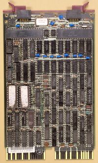
The MXV11-A Multifunction Option Module is a QBUS dual-height peripheral board (M8047), intended to allow the creation of complete systems in a minimal-sized QBUS backplane.
It contains two asynchronous serial lines (using the DL11 programming standard), an optional non-programmable line time clock, a block of main memory, and some PROM for bootstrap purposes. The serial lines are connected via 10-pin Berg connector headers on the top edge of the card, using the standard DEC asynchronous serial line pinout, and line 1 can be set to halt or boot the machine on a break.
Two different versions exist:
- MXV11-AA - 8Kbytes of RAM
- MXV11-AC - 32Kbytes of RAM
It is a Q18 device, and the RAM cannot be used when it is in a Q22 system.
See also
Further reading
- MXV11 Configuration, MicroNote #054
- MXV11-AA, -AC Cabling, MicroNote #074
- Alternate Clock Frequencies for the MXV11, MicroNote #083
- MXV11 Bootstrap Problems, MicroNote #105
- MXV11 Functionality, MicroNote #106
External links
- microcomputer processor handbook - the MXV11-A is covered in Chapter 12, pp. 494-493 (pp. 531-541 of the PDF)
- Microcomputer Products Handbook - the MXV11-A is covered on pp. 17–1-21 (pp. 231-251 of the PDF)
- MXV11-AA, AC Configuration Guide (M8047)
- MXV11-A Field Maintenance Print Set (MP00730)
- Multifunction Modules
