Difference between revisions of "DEC power distribution connectors"
(Add link to DIgikey page for them) |
m (+link) |
||
| (18 intermediate revisions by the same user not shown) | |||
| Line 1: | Line 1: | ||
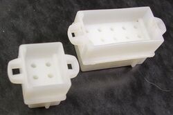
| − | + | [[Image:DECPwrConnFemales.jpg|250px|thumb|right|Female shells]] | |
| − | + | Many [[Digital Equipment Corporation|DEC]] [[PDP-11]] [[backplane]] [[system unit]]s use a common system of connectors to the [[power harness]] which leads from the [[power supply]]. | |
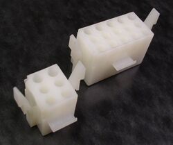
| − | + | They were connected to the harness (which usually ended in a power distribution panel) using multi-[[pin]] AMP MATE-N-LOK connectors: the connectors on the panel used male shells (housings) with female pins; all the cables from the backplanes had female shells, with male pins. | |
| + | |||
| + | Generally the [[DEC standard power wire colour coding]] was used. | ||
| + | |||
| + | ==Pinouts== | ||
| + | |||
| + | Some early machines (e.g. the early versions of the [[PDP-11/05]]) used 9-pin connectors; all the later machines and [[mounting box]]es used pairs of 6-pin and 15-pin connectors. | ||
| + | |||
| + | The pinout of the 9-pin connector is: | ||
| + | |||
| + | {| class="wikitable" | ||
| + | ! Pin !! Signal | ||
| + | |- | ||
| + | | 1 || DCLO | ||
| + | |- | ||
| + | | 2 || ACLO | ||
| + | |- | ||
| + | | 3 || -15V | ||
| + | |- | ||
| + | | 4 || [[Ground]] | ||
| + | |- | ||
| + | | 5 || Ground | ||
| + | |- | ||
| + | | 6 || Ground | ||
| + | |- | ||
| + | | 7 || [[Line time clock|LTC]] | ||
| + | |- | ||
| + | | 8 || +15V | ||
| + | |- | ||
| + | | 9 || +5V | ||
| + | |} | ||
| + | |||
| + | Pin 1 is the pin nearest the ridge on the side of the shell; there are two corner keys on the 7-9 side of the shell, on the inside. | ||
| + | |||
| + | [[Image:DECPwrConnMales.jpg|250px|thumb|right|Male shells]] | ||
| + | |||
| + | The pinouts of the 6-pin and 15-pin connector are: | ||
| + | |||
| + | {| class="wikitable" | ||
| + | ! Pin !! Signal | ||
| + | |- | ||
| + | | 1 || Ground | ||
| + | |- | ||
| + | | 2 || LTC | ||
| + | |- | ||
| + | | 3 || DCLO | ||
| + | |- | ||
| + | | 4 || ACLO | ||
| + | |- | ||
| + | | 5 || Unused | ||
| + | |- | ||
| + | | 6 || Unused | ||
| + | |} | ||
| + | |||
| + | Again, pin 1 is the pin nearest the ridge on the side of the shell, and there are two corner keys on the 4-6 side of the shell, on the inside. | ||
| + | |||
| + | {| class="wikitable" | ||
| + | ! Pin !! Signal | ||
| + | |- | ||
| + | | 1 || +5V | ||
| + | |- | ||
| + | | 2 || +15V | ||
| + | |- | ||
| + | | 3 || +20V '''or''' +15VC | ||
| + | |- | ||
| + | | 4 || +5V | ||
| + | |- | ||
| + | | 5 || Ground | ||
| + | |- | ||
| + | | 6 || +15B (Battery backup) | ||
| + | |- | ||
| + | | 7 || Ground | ||
| + | |- | ||
| + | | 8 || Ground | ||
| + | |- | ||
| + | | 9 || Ground | ||
| + | |- | ||
| + | | 10 || +5B (Battery backup)<sup>1</sup> | ||
| + | |- | ||
| + | | 11 || Ground | ||
| + | |- | ||
| + | | 12 || +5B (Battery backup)<sup>2</sup> | ||
| + | |- | ||
| + | | 13 || -15V | ||
| + | |- | ||
| + | | 14 || -5V | ||
| + | |- | ||
| + | | 15 || -15B (Battery backup) | ||
| + | |} | ||
| + | |||
| + | 1 - [[BA11-F Mounting Box]]<br> | ||
| + | 2 - [[BA11-K mounting box]] | ||
| + | |||
| + | Once again, pin 1 is the pin nearest the ridge on the side of the shell, and there are two corner keys on the 13-15 side of the shell, on the inside. | ||
| + | |||
| + | Not all supplies/harnesses provided the battery backup voltages. | ||
| + | |||
| + | '''''Note:''''' In the [[BA11-A mounting box]] used with the [[PDP-11/24]] (but ''not'' in the [[BA11-L mounting box|BA11-L]] version of the -11/24), pins 6 and 15 are +12V/-12V, allowing use of the [[MS11-M MOS memory]]; pin 3 is +15VC. | ||
| + | |||
| + | ==Connectors== | ||
| + | |||
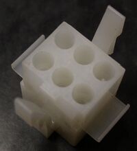
| + | [[Image:DECPwrConnMaleSml.jpg|200px|thumb|right|9-pin Male shell, close-up]] | ||
The AMP part numbers for the shells (AMP calls the female housings 'caps', and the male housings 'plugs') are below: | The AMP part numbers for the shells (AMP calls the female housings 'caps', and the male housings 'plugs') are below: | ||
| Line 17: | Line 118: | ||
|} | |} | ||
| − | + | An alternative 6-pin male shell is AMP 1-171196-0; it is compatible with the ones listed here, but is not one that DEC used, as far as is currently known. | |
| + | |||
| + | The female pins (sockets, functionally) are AMP part number 60619-1; the male pins are 60620-1. (There are a large number of different pin options: 30-22, 24-18, and 20-14 gauge; tin and gold plated; and brass and phosphor-bronze material. The part numbers given are for tinned brass, 20-14 gauge.) | ||
AMP has been bought by TE Connectivity, but these MATE-N-LOK connectors are still in production, and available from the usual suppliers. | AMP has been bought by TE Connectivity, but these MATE-N-LOK connectors are still in production, and available from the usual suppliers. | ||
| + | |||
| + | The [[DEC part number]]s for the male shells are 12-09350-06 and -15; the female shell numbers are 12-09351-06 and -15. These numbers are more historical curiosities than anything else; the AMP numbers, already given above, are what is needed to order them. | ||
==External links== | ==External links== | ||
| Line 25: | Line 130: | ||
* [https://www.digikey.com/products/en?FV=ffec0ef5 Digikey's page for the line] - click on 'Housings' at the bottom | * [https://www.digikey.com/products/en?FV=ffec0ef5 Digikey's page for the line] - click on 'Housings' at the bottom | ||
| − | [[Category: DEC | + | [[Category: DEC Electrical]] |
Latest revision as of 15:29, 15 July 2023
Many DEC PDP-11 backplane system units use a common system of connectors to the power harness which leads from the power supply.
They were connected to the harness (which usually ended in a power distribution panel) using multi-pin AMP MATE-N-LOK connectors: the connectors on the panel used male shells (housings) with female pins; all the cables from the backplanes had female shells, with male pins.
Generally the DEC standard power wire colour coding was used.
Pinouts
Some early machines (e.g. the early versions of the PDP-11/05) used 9-pin connectors; all the later machines and mounting boxes used pairs of 6-pin and 15-pin connectors.
The pinout of the 9-pin connector is:
| Pin | Signal |
|---|---|
| 1 | DCLO |
| 2 | ACLO |
| 3 | -15V |
| 4 | Ground |
| 5 | Ground |
| 6 | Ground |
| 7 | LTC |
| 8 | +15V |
| 9 | +5V |
Pin 1 is the pin nearest the ridge on the side of the shell; there are two corner keys on the 7-9 side of the shell, on the inside.
The pinouts of the 6-pin and 15-pin connector are:
| Pin | Signal |
|---|---|
| 1 | Ground |
| 2 | LTC |
| 3 | DCLO |
| 4 | ACLO |
| 5 | Unused |
| 6 | Unused |
Again, pin 1 is the pin nearest the ridge on the side of the shell, and there are two corner keys on the 4-6 side of the shell, on the inside.
| Pin | Signal |
|---|---|
| 1 | +5V |
| 2 | +15V |
| 3 | +20V or +15VC |
| 4 | +5V |
| 5 | Ground |
| 6 | +15B (Battery backup) |
| 7 | Ground |
| 8 | Ground |
| 9 | Ground |
| 10 | +5B (Battery backup)1 |
| 11 | Ground |
| 12 | +5B (Battery backup)2 |
| 13 | -15V |
| 14 | -5V |
| 15 | -15B (Battery backup) |
1 - BA11-F Mounting Box
2 - BA11-K mounting box
Once again, pin 1 is the pin nearest the ridge on the side of the shell, and there are two corner keys on the 13-15 side of the shell, on the inside.
Not all supplies/harnesses provided the battery backup voltages.
Note: In the BA11-A mounting box used with the PDP-11/24 (but not in the BA11-L version of the -11/24), pins 6 and 15 are +12V/-12V, allowing use of the MS11-M MOS memory; pin 3 is +15VC.
Connectors
The AMP part numbers for the shells (AMP calls the female housings 'caps', and the male housings 'plugs') are below:
| Pin count | Male shell | Female shell |
|---|---|---|
| 6 | 1-480273-0 | 1-480276-0 |
| 9 | 1-480274-0 | 1-480277-0 |
| 15 | 1-480323-0 | 1-480324-0 |
An alternative 6-pin male shell is AMP 1-171196-0; it is compatible with the ones listed here, but is not one that DEC used, as far as is currently known.
The female pins (sockets, functionally) are AMP part number 60619-1; the male pins are 60620-1. (There are a large number of different pin options: 30-22, 24-18, and 20-14 gauge; tin and gold plated; and brass and phosphor-bronze material. The part numbers given are for tinned brass, 20-14 gauge.)
AMP has been bought by TE Connectivity, but these MATE-N-LOK connectors are still in production, and available from the usual suppliers.
The DEC part numbers for the male shells are 12-09350-06 and -15; the female shell numbers are 12-09351-06 and -15. These numbers are more historical curiosities than anything else; the AMP numbers, already given above, are what is needed to order them.
External links
- Digikey's page for the line - click on 'Housings' at the bottom


