Difference between revisions of "KD11-D CPU"
(Details on RTT) |
(Clarify KY11-LB microcode diagnostic physical interface) |
||
| (3 intermediate revisions by the same user not shown) | |||
| Line 1: | Line 1: | ||
[[Image:1104CPU_M7263.jpg|250px|right|thumb|A KD11-D card.]] | [[Image:1104CPU_M7263.jpg|250px|right|thumb|A KD11-D card.]] | ||
| − | The '''KD11-D''' [[PDP-11]] [[Central Processing Unit|CPU]] of the [[PDP-11/04]] was a [[microcode|micro-programmed]] processor contained on single [[DEC card form factor|hex]] [[printed circuit board|card]] (the M7263), the first PDP-11 CPU to be built on a single card. | + | The '''KD11-D''' [[PDP-11]] [[Central Processing Unit|CPU]] of the [[PDP-11/04]] was a [[microcode|micro-programmed]] processor (making heavy use of [[Read-only memory#PROM|PROMs]]). It was contained on single [[DEC card form factor|hex]] [[printed circuit board|card]] (the M7263), the first PDP-11 CPU to be built on a single card. |
Like other early, low-cost PDP-11s, it did not support either [[memory management]] of any kind, or hardware [[floating point]], [[PDP-11 Extended Instruction Set|EIS]] [[instruction]]s, or the various instructions added to the PDP-11 [[instruction set]] (XOR, SOB, SXT and MARK). | Like other early, low-cost PDP-11s, it did not support either [[memory management]] of any kind, or hardware [[floating point]], [[PDP-11 Extended Instruction Set|EIS]] [[instruction]]s, or the various instructions added to the PDP-11 [[instruction set]] (XOR, SOB, SXT and MARK). | ||
| Line 7: | Line 7: | ||
There is a lack of clarity over the RTT instruction; the ''pdp11 04/05/10/35/40/45 processor handbook'' says it is not implemented, but the ''PDP-11 Architecture Handbook'' says "available in 11/04 but is different from other implementations"; the ''KD11-D Processor Manual'' (EK-KD11D-TM-PRE) says the "first instruction after RTT is guaranteed to be executed" - the same as the [[KD11-A CPU]]. | There is a lack of clarity over the RTT instruction; the ''pdp11 04/05/10/35/40/45 processor handbook'' says it is not implemented, but the ''PDP-11 Architecture Handbook'' says "available in 11/04 but is different from other implementations"; the ''KD11-D Processor Manual'' (EK-KD11D-TM-PRE) says the "first instruction after RTT is guaranteed to be executed" - the same as the [[KD11-A CPU]]. | ||
| − | It plugs into a modified [[Modified UNIBUS Device|MUD]] [[backplane]] | + | It plugs into a modified [[Modified UNIBUS Device|MUD]] [[backplane]]; either the [[DD11-C backplane|DD11-C]] or [[DD11-D backplane]]s, or the special [[DD11-P backplane]] of the [[PDP-11/34]]. |
| − | + | ==KY11-L support== | |
| − | + | It supported the [[KY11-LA Operator's Console]] and the [[KY11-LB Programmer's Console]], including the latter's maintenance functionality which allowed the CPU's [[microcode]] to be [[single-step]]ped. The KD11-D uses the same [[KY11-L to CPU interface]] as the other machines that use them. | |
| − | The microcode diagnostic interface to the KY11-LB is carried over a 10-wire [[flat cable]] connected to the J2 [[Berg connector]] header on the KY11-LB's M7859 module (the other 10-pin header on that card is unused with the -11/04), and a set of vertical [[pin]]s in the upper left-hand corner (see image above) | + | The microcode diagnostic interface to the KY11-LB is carried over a 10-wire [[flat cable]] connected to i) the J2 [[Berg connector]] header on the KY11-LB's M7859 module (the other 10-pin header on that card is unused with the -11/04), and ii) to a set of bare vertical [[pin]]s in the upper left-hand corner of the M7263 (see image above; between the 3rd and 4th [[integrated circuit|chips]] in the top row). (The main functionality of the KY11-B is done over the [[UNIBUS]], and a pair of backplane lines.) |
| − | + | ==External links== | |
| − | [[Category:PDP-11 Processors]] | + | * [http://www.bitsavers.org/www.computer.museum.uq.edu.au/pdf/EK-KD11D-TM-PRE%20KD11-D%20Processor%20Manual%20(PDP-11-04).pdf KD11-D Processor Manual (PDP-11/04)] (EK-KD11D-TM-PRE) |
| − | [[Category: | + | * [http://www.bitsavers.org/pdf/dec/pdp11/1104/MP00019_1104_EngrDrws_Feb78.pdf PDP-11/04 engineering drawings] - Contains KD11-D Field Maintenance Print Set (MP00020) on pp. 167-276 of the PDF(includes complete PROM dumps) |
| + | |||
| + | [[Category: PDP-11 UNIBUS Processors]] | ||
| + | [[Category: DEC Documentation Errors]] | ||
Latest revision as of 21:03, 27 November 2024
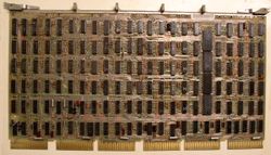
The KD11-D PDP-11 CPU of the PDP-11/04 was a micro-programmed processor (making heavy use of PROMs). It was contained on single hex card (the M7263), the first PDP-11 CPU to be built on a single card.
Like other early, low-cost PDP-11s, it did not support either memory management of any kind, or hardware floating point, EIS instructions, or the various instructions added to the PDP-11 instruction set (XOR, SOB, SXT and MARK).
There is a lack of clarity over the RTT instruction; the pdp11 04/05/10/35/40/45 processor handbook says it is not implemented, but the PDP-11 Architecture Handbook says "available in 11/04 but is different from other implementations"; the KD11-D Processor Manual (EK-KD11D-TM-PRE) says the "first instruction after RTT is guaranteed to be executed" - the same as the KD11-A CPU.
It plugs into a modified MUD backplane; either the DD11-C or DD11-D backplanes, or the special DD11-P backplane of the PDP-11/34.
KY11-L support
It supported the KY11-LA Operator's Console and the KY11-LB Programmer's Console, including the latter's maintenance functionality which allowed the CPU's microcode to be single-stepped. The KD11-D uses the same KY11-L to CPU interface as the other machines that use them.
The microcode diagnostic interface to the KY11-LB is carried over a 10-wire flat cable connected to i) the J2 Berg connector header on the KY11-LB's M7859 module (the other 10-pin header on that card is unused with the -11/04), and ii) to a set of bare vertical pins in the upper left-hand corner of the M7263 (see image above; between the 3rd and 4th chips in the top row). (The main functionality of the KY11-B is done over the UNIBUS, and a pair of backplane lines.)
External links
- KD11-D Processor Manual (PDP-11/04) (EK-KD11D-TM-PRE)
- PDP-11/04 engineering drawings - Contains KD11-D Field Maintenance Print Set (MP00020) on pp. 167-276 of the PDF(includes complete PROM dumps)
