Difference between revisions of "RL01/02 disk drive"
(→Cabling: Add cable info) |
(Add ext link) |
||
| Line 33: | Line 33: | ||
To keep the [[head]]s properly aligned on the [[track]]s, it used a servo system driven by servo data written on the pack (along with [[sector]] headers) at the factory. Packs ''cannnot'' be low-level re-formatted in the field, and are not compatible with both drive types. | To keep the [[head]]s properly aligned on the [[track]]s, it used a servo system driven by servo data written on the pack (along with [[sector]] headers) at the factory. Packs ''cannnot'' be low-level re-formatted in the field, and are not compatible with both drive types. | ||
| + | |||
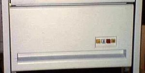
| + | [[Image:rl02drive.jpg|150px|thumb|left|An RL02 drive]] | ||
Early versions of the drives included a set of brushes that swing out over the [[platter]] on start-up; these were deleted in later versions. | Early versions of the drives included a set of brushes that swing out over the [[platter]] on start-up; these were deleted in later versions. | ||
| − | + | Up to 4 drives may be attached to a single controller; the drives are connected serially. | |
| − | |||
| − | Up to 4 drives may be attached to a single controller; the drives are connected serially | ||
| − | The [[UNIBUS]] | + | The [[UNIBUS]] controller is the [[RL11 disk controller|RL11]], a single [[DEC card form factor|hex]] card. The [[QBUS]] controllers are the [[RLV11]] and [[RLV12]]; the former consists of two [[DEC card form factor|quad]] cards, and needs a QBUS [[backplane]] with [[CD interconnect]]; the latter is a single quad card, and is also the [[QBUS|Q22]] version. |
==Cabling== | ==Cabling== | ||
| Line 50: | Line 50: | ||
To get from the controller to the first drive of the string, one of two setups can be used. A BC80M-xx cable has a [[Berg connector]] at one end which plugs into the controller, and one of the latching connectors at the other. Alternatively, a BC06R-xx [[flat cable]] goes from the controller to a transition adapter in a mounting bracket attached to the rack; a standard BC20J cable goes from there to the first drive. | To get from the controller to the first drive of the string, one of two setups can be used. A BC80M-xx cable has a [[Berg connector]] at one end which plugs into the controller, and one of the latching connectors at the other. Alternatively, a BC06R-xx [[flat cable]] goes from the controller to a transition adapter in a mounting bracket attached to the rack; a standard BC20J cable goes from there to the first drive. | ||
| − | The drive string must be ended with a terminator, part number 70-12293-0-0 (although the terminators generally have no markings on them). | + | The drive string must be ended with a [[terminator]] on the 'out' port of the last drive, part number 70-12293-0-0 (although the terminators generally have no markings on them). |
The terminators for the RL0x and RK06/07 drives are the same, and interchangeable. The cables are semi-compatible; RK06/7 cables may be used with the RL0x, but not the other way around - those for the RK06/07 have additional wires which are not present in the RL0x cables. | The terminators for the RL0x and RK06/07 drives are the same, and interchangeable. The cables are semi-compatible; RK06/7 cables may be used with the RL0x, but not the other way around - those for the RK06/07 have additional wires which are not present in the RL0x cables. | ||
| Line 69: | Line 69: | ||
* [http://www.pdp11gy.com/doneE.html Home page of project] | * [http://www.pdp11gy.com/doneE.html Home page of project] | ||
* [http://www.vintage-computer.com/vcforum/album.php?albumid=184&attachmentid=12300 Picture of the simulator connected to a PDP-11/53] | * [http://www.vintage-computer.com/vcforum/album.php?albumid=184&attachmentid=12300 Picture of the simulator connected to a PDP-11/53] | ||
| + | |||
| + | ==External links== | ||
| + | |||
| + | * [http://www.pdp-11.nl/peripherals/disk/rl-info.html RL01 / RL02 removable hard disk drive] | ||
[[Category: DEC Disk Drives]] | [[Category: DEC Disk Drives]] | ||
Revision as of 17:01, 30 December 2017
| RL01 / RL02 | |
| Manufacturer: | Digital Equipment Corporation |
|---|---|
| Drive Controller(s): | RL11 (UNIBUS) |
| Capacity: | 5.2 Mbytes (formatted) (RL01) 10.4 Mbytes (formatted) (RL02) |
| Transfer Rate: | 512 Kbytes/sec 3.9 usec/word (peak) |
| Average Access Time: | 67.5 msec |
| Revolutions per Minute: | 2400 |
| 1/2 Revolution Time: | 12.5 msec |
| One Track Seek Time: | 15 msec |
| Average Seek Time: | 55 msec |
| Maximum Seek Time: | 100 msec |
| Head Switching Time: | 8 msec (maximum) |
| Total Surfaces: | 2 |
| Tracks per Surface: | 256 (RL01) 512 (RL02) |
| Sectors per Track: | 40 |
| Words per Sector: | 128 |
| Tracks per Inch: | 125 (RL01) 250 (RL02) |
| Density: | 3725 bpi (maximum) |
| Recording Method: | Modified Frequency Modulation (MFM) |
| Start Time: | 40 seconds |
| Stop Time: | 30 seconds |
| Physical Size: | 19" W x 10-1/2" H x 25" L |
| Weight: | 55 pounds |
| Power Consumption: | 160W (running); 550 VA (starting) |
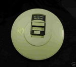
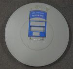
The RL01 and RL02 are single platter, removable pack disk drives, introduced in 1976 and 1978 respectively, by DEC. They used an IBM 5440 type pack, as used on the IBM System/3.
The RL01 is a 5MiB drive, and the RL02 is 10MiB; the latter is a high-density version, with twice as many tracks per surface, but otherwise mostly identical.
To keep the heads properly aligned on the tracks, it used a servo system driven by servo data written on the pack (along with sector headers) at the factory. Packs cannnot be low-level re-formatted in the field, and are not compatible with both drive types.
Early versions of the drives included a set of brushes that swing out over the platter on start-up; these were deleted in later versions.
Up to 4 drives may be attached to a single controller; the drives are connected serially.
The UNIBUS controller is the RL11, a single hex card. The QBUS controllers are the RLV11 and RLV12; the former consists of two quad cards, and needs a QBUS backplane with CD interconnect; the latter is a single quad card, and is also the Q22 version.
Cabling
The RL0x uses a cable with latching connectors at each end to go between drives; the part number is 70-12122-xx (where xx is the length, one of 10, 20, 40 or 60); it is also known as a BC20J-xx.
To get from the controller to the first drive of the string, one of two setups can be used. A BC80M-xx cable has a Berg connector at one end which plugs into the controller, and one of the latching connectors at the other. Alternatively, a BC06R-xx flat cable goes from the controller to a transition adapter in a mounting bracket attached to the rack; a standard BC20J cable goes from there to the first drive.
The drive string must be ended with a terminator on the 'out' port of the last drive, part number 70-12293-0-0 (although the terminators generally have no markings on them).
The terminators for the RL0x and RK06/07 drives are the same, and interchangeable. The cables are semi-compatible; RK06/7 cables may be used with the RL0x, but not the other way around - those for the RK06/07 have additional wires which are not present in the RL0x cables.
4.3 BSD disktab
rb02|RB02|DEC RL02 on 730 IDC:\
    :ty=removable:se#256:ns#40:nt#2:nc#32:\
    :pa#15884:ba#4096:fa#1024:\
    :pb#4480:pc#20480:
Emulating the RL02
Reinhard Heuberger has created an open source emulator for the RL02 (and RL01) using a Terasic DE0-Nano Altera Cyclone IV FPGA board, extended with necessary interfacing hardware and an SD card slot. The emulator can be used with a real PDP-11, for example.
* Home page of project
* Picture of the simulator connected to a PDP-11/53


