Difference between revisions of "DLV11-E asynchronous serial line interface"
(+img) |
(+img rev D etch) |
||
| Line 1: | Line 1: | ||
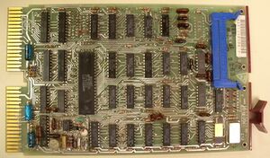
[[Image:DLV11-E RevC.jpg|thumb|right|300px|DLV11-E M8017 board etch revision C]] | [[Image:DLV11-E RevC.jpg|thumb|right|300px|DLV11-E M8017 board etch revision C]] | ||
| − | The '''DLV11-E asynchronous serial line interface''' card | + | The '''DLV11-E asynchronous serial line interface''' card was a [[QBUS]] [[peripheral]] for the [[PDP-11]] series of computers which provided an [[asynchronous serial line]] on a single [[DEC card form factor|dual-width]] card ('''M8017''') . |
It provided [[EIA RS-232 serial line interface|EIA RS-232]] connectivity; it also had full [[modem]] control. [[Baud rate]]s from 50 to 19,200 were available; receive and transmit can be set independently via configuration [[jumper]]s, or can be set via the [[register]]s, if desired (although not independently; either transmit only, or both). | It provided [[EIA RS-232 serial line interface|EIA RS-232]] connectivity; it also had full [[modem]] control. [[Baud rate]]s from 50 to 19,200 were available; receive and transmit can be set independently via configuration [[jumper]]s, or can be set via the [[register]]s, if desired (although not independently; either transmit only, or both). | ||
| Line 14: | Line 14: | ||
The first line after the console is always assigned the address 0776500, and vector 0300. Additional lines are assigned addresses and vectors immediately following, for DL11's #1-#16 (i.e. 0776500-676 and 0300-0476). | The first line after the console is always assigned the address 0776500, and vector 0300. Additional lines are assigned addresses and vectors immediately following, for DL11's #1-#16 (i.e. 0776500-676 and 0300-0476). | ||
| + | |||
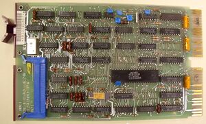
| + | [[Image:DLV11-E RevD.jpg|thumb|left|300px|DLV11-E M8017 board etch revision D]] | ||
==Layout== | ==Layout== | ||
Revision as of 22:42, 25 October 2020
The DLV11-E asynchronous serial line interface card was a QBUS peripheral for the PDP-11 series of computers which provided an asynchronous serial line on a single dual-width card (M8017) .
It provided EIA RS-232 connectivity; it also had full modem control. Baud rates from 50 to 19,200 were available; receive and transmit can be set independently via configuration jumpers, or can be set via the registers, if desired (although not independently; either transmit only, or both).
Line connection was via 40-pin Berg connector headers on the top edge of the card, using the standard DEC asynchronous serial line pinout.
Programing interface
Like the ancestral KL11, the DLV11 has 2 device registers for the receive side (one Control and Status Register - CSR - and one data buffer register), and similarly, two for the transmit side. Each line has two interrupt vectors - again, one receive, and one transmit.
For the PDP-11 main console (which is always a KL11/DL11 compatible device), the standard is that 0777560 is the base address (so the receiver registers are 0777560-2, and the transmitter are 0777564-6), and 060 is the base vector. It can be set to halt the CPU, or re-boot the system, when a 'break' is seen; it can also send a 'break'.
The first line after the console is always assigned the address 0776500, and vector 0300. Additional lines are assigned addresses and vectors immediately following, for DL11's #1-#16 (i.e. 0776500-676 and 0300-0476).
Layout
The 'Revison D' PCB layout is significantly different from the earlier ones; it is easy to recognize this version visually, as the large UART chip is parallel to the long axis of the card. This version is not covered in most DLV11-E documentation; it can be found in the "Microcomputer Products Handbook" (1985), on pg. 22-3.

