Difference between revisions of "DRV11-WA General Purpose DMA Interface"
m (proper sub-cat) |
(→External links: +Manuals, eng drws - also diag loopback) |
||
| Line 5: | Line 5: | ||
It is effectively a [[half-duplex]] device; it has only a single pair of [[bus]] [[address]] and word count [[register]]s. Directional control is by the [[user]]'s device specifying whether each cycle is a DATI, DATO, or DATIO. | It is effectively a [[half-duplex]] device; it has only a single pair of [[bus]] [[address]] and word count [[register]]s. Directional control is by the [[user]]'s device specifying whether each cycle is a DATI, DATO, or DATIO. | ||
| − | It was a [[DEC card form factor|dual]] format card (M7651); connection to the user's device is via a pair of 40-[[pin]] [[Berg connector]]s. | + | It was a [[DEC card form factor|dual]] format card (M7651); connection to the user's device is via a pair of 40-[[pin]] [[Berg connector]]s. For [[diagnostic]] purposes, a BC05L cable can be used to loop the device's input and output together. |
==Registers== | ==Registers== | ||
| Line 68: | Line 68: | ||
{{16bit-bitout}} | {{16bit-bitout}} | ||
--> | --> | ||
| + | |||
| + | ==External links== | ||
| + | |||
| + | * [http://www.vaxhaven.com/images/8/80/EK-DRVWA-UG-001.pdf DRV11-WA General Purpose DMA Interface User's Guide] (EK-DRVWA-UG-001) | ||
| + | * [http://www.bitsavers.org/pdf/dec/qbus/EK-DRVWA-UG-002_DRV11W_UG.pdf DRV11-WA General Purpose DMA Interface User's Guide] (EK-ORVWA-UG-002) | ||
| + | * [http://www.bitsavers.org/pdf/dec/qbus/MP01582_DRV11-WA_EngrDrws.pdf DRV11-WA Field Maintenance Print Set] (MP01582-01) | ||
| + | |||
[[Category: QBUS Parallel Interfaces]] | [[Category: QBUS Parallel Interfaces]] | ||
Latest revision as of 17:12, 2 December 2021
The DRV11-WA Direct Memory Access Interface is a parallel interface device controller for the QBUS which provided a pair of 16-bit parallel ports, one input, and one output. It uses DMA to transfer data; it is a Q22 device.
It is effectively a half-duplex device; it has only a single pair of bus address and word count registers. Directional control is by the user's device specifying whether each cycle is a DATI, DATO, or DATIO.
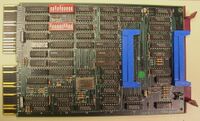
It was a dual format card (M7651); connection to the user's device is via a pair of 40-pin Berg connectors. For diagnostic purposes, a BC05L cable can be used to loop the device's input and output together.
Registers
The device has six control and buffer registers, which can be configured to any group of four sequential word locations in the I/O page (two pairs of registers share an address); the first DRV11-WA is normally configured to addresses 772410-72416.
| Register | Abbreviation | Address |
|---|---|---|
| Word Count Register | DRWCR | 767770 |
| Bus Address Register | DRBAR | 767772 |
| Bus Address Extension Register | DRBAE | 767772 |
| Control and Status Register | DRCSR | 767774 |
| Input Data Buffer Register | DRINBUF | 767776 (read) |
| Output Data Buffer Register | DROUTBUF | 767776 (write) |
To gain access to the BAE, reference the BAR; this sets an internal flag which sends the next reference to the BAR's address to the BAE. Referring to any register (e.g. reading the WCR) clears the flag. The two buffer registers share an address, responding to read or write cycles as the case might be.
External links
- DRV11-WA General Purpose DMA Interface User's Guide (EK-DRVWA-UG-001)
- DRV11-WA General Purpose DMA Interface User's Guide (EK-ORVWA-UG-002)
- DRV11-WA Field Maintenance Print Set (MP01582-01)
