Difference between revisions of "DEC Power Line Monitor"
(Fairly complete) |
m (New cat) |
||
| Line 27: | Line 27: | ||
* [http://www.glitchwrks.com/2019/06/05/pdp1110-psu-repair Repairing the PDP-11/10 Power Supply] | * [http://www.glitchwrks.com/2019/06/05/pdp1110-psu-repair Repairing the PDP-11/10 Power Supply] | ||
| − | [[Category: DEC | + | [[Category: DEC Electrical]] |
Latest revision as of 23:13, 15 June 2022
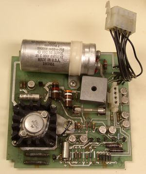
A DEC Power Line Monitor (alternatively called a Power Control Board, Regulator Board and +15V DC regulator in various DEC documents and maintenance prints) is a small board used in the H742/H7420 and H765 power supplies to produce a modest amount of +15V DC power, along with a line time clock signal, and AC and DC 'power OK' signals.
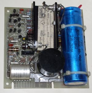
The initial board was the 5409730 board in the H742, replaced by an 5411086 board in the H7420; the latter board was also used in the H765. The main difference beween the two was that the latter had been upgraded to produce up to 4A of -15V, from the 1A of the former.
There were also significant differences between the two in how they interfaced to the rest of the system; the main difference beween the two was that the former produced outputs on a short pigtail which ran into a 12-pin Mate-n-Lok connector (female pins), whereas the latter has an edge connector which plugs into a connector at one end of a power harness.
The latter was probably to allow use of different harnesses in different applications: the H7420 harness, for instance, terminates in a Mate-n-Lok connector with female pins, emulating the original H742; the H765 harness ends in a Mate-n-Loc connector with male pins, apparently to allow the mating connector on the power distribution panel to have female pins, in common with all the other connectors on that panel.
Other uses (such as in the MJ11 and MK11 memory systems) use different harnesses.
The former version of the board also brings its AC input in on a 4-pin Mate-n-Lok connector secured to the board; the latter uses the two right-most contacts (in the image to the side); these are usually broken out to a separate connector in the harness (see, for example, the 7010138 harness used in the standard BA11-K.
Issues
Some components on the 5411086 board (such as the main bridge rectifier) are not protected by an on-board fuse; if they fail 'closed', since AC to that board enters through contacts on the edge connector, those contacts may be damaged.
This is not an issue in the H7420, which has a fuse in the power harness feeding the card; the H765 has no such fuse, and the issue has been seen in the field with these units.
It is recommended that an in-line fuse be added to the supply harness in these units. Alternatively, a separate AC supply pigtail, holding an in-line fuse, can be installed, to avoid routing AC through the edge connector at all; this approach has the additional advantage of not needing a change to the original harness in the unit.

