Difference between revisions of "KDF11-A CPU"
m (→External links: Narrow category) |
m (rm bloat) |
||
| Line 69: | Line 69: | ||
* [http://www.bitsavers.org/pdf/dec/pdp11/1123/EK-KDF11-UG-PR2_Mar79.pdf KDF11-AA User's Guide] (EK-KDF11-UG-PR2) | * [http://www.bitsavers.org/pdf/dec/pdp11/1123/EK-KDF11-UG-PR2_Mar79.pdf KDF11-AA User's Guide] (EK-KDF11-UG-PR2) | ||
* [http://www.bitsavers.org/pdf/dec/pdp11/1123/MP00734_KDF11A_EngrDrws.pdf KDF11-A Field Maintenance Print Set] (MP00734) | * [http://www.bitsavers.org/pdf/dec/pdp11/1123/MP00734_KDF11A_EngrDrws.pdf KDF11-A Field Maintenance Print Set] (MP00734) | ||
| − | |||
| − | |||
[[Category: PDP-11 QBUS Processors]] | [[Category: PDP-11 QBUS Processors]] | ||
Revision as of 19:05, 2 July 2023
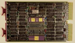
The KDF11-A CPU is a PDP-11 CPU for the QBUS; it is a dual-width card, the M8186. It uses the same 'Fonz' F-11 chip set as the other KDF11 CPUs.
It contains only the basic CPU, unlike the other KDF-11's: no ROM, no asynchronous serial lines, etc. It does support the optional KTF11-A memory management chip and the KEF11-A floating point chip, but not the KEF11-B PDP-11 Commercial Instruction Set (CIS); for higher performance floating point, the FPF11 floating point processor may be used.
The first version of the KDF11-A (Revision A) only suppported 256 Kbytes of main memory; later versions supported up to 4 Mbytes (but their ODT's address space is limited to 256 Kbytes). In the later models, a bit in the SSR3 CPU register must be set to allow use of more than 256 Kbytes.
Configuration
A limited amount of configuration can be done with a number of jumpers in various locations (which differ depending on etch revision, with block of eleven in the middle of the card.Their functions are:
| Jumper | Function | In | Out |
|---|---|---|---|
| W1 | Master Clock | Enabled | Disabled |
| W2 | Reserved | Factory | Do not remove |
| W3 | Unknown | ||
| W4 | Event line | Disabled | Enabled |
| W5 | Powerup option bit 1 | ||
| W6 | Powerup option bit 2 | ||
| W7 | Halt enable | Halt | Trap to 4 |
| W8 | Bootstrap address 0173000 | Yes | W9-W15 |
| W09 | Bootstrap address bit 9 | 1 | 0 |
| W10 | Bootstrap address bit 10 | 1 | 0 |
| W11 | Bootstrap address bit 11 | 1 | 0 |
| W12 | Bootstrap address bit 12 | 1 | 0 |
| W13 | Bootstrap address bit 13 | 1 | 0 |
| W14 | Bootstrap address bit 14 | 1 | 0 |
| W15 | Bootstrap address bit 15 | 1 | 0 |
| W16 | Reserved | Factory | Do not remove |
| W17 | Reserved | Factory | Do not remove |
| W18 | Wakeup circuit | Disabled | Enabled |
Powerup options are:
| W6 | W5 | Action |
|---|---|---|
| Out | Out | PC from 024, PS from 026 |
| Out | In | ODT |
| In | Out | PC=configuration jumpers |
| In | In | Extended microcode (trap to 010 if none) |
External links
- KDF11-AA User's Guide (EK-KDF11-UG-PR2)
- KDF11-A Field Maintenance Print Set (MP00734)
