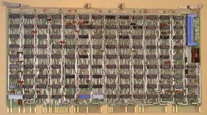
The DUP11 is an early synchronous serial line interface for the UNIBUS. Like the earlier DP11-A, it used programmed I/O (with separate receive and transmit interrupts) to transfer data; it was double-buffered for both input and output. It could operate in either half-duplex or full-duplex, at baud rates up to 9.6K bits/second.
Both byte-oriented (e.g. DDCMP, BISYNC) and bit-oriented (e.g. SDLC, HDLC) protocols were supported; a variety of CRC algorithms, depending on the[protocol in use on the line, were supported for error detection. The character length was 8 bits; the sync character was selectable under program control, as well as the modem control leads. It apparently supported idling (sending the sync character); the line could also be set to a mark condition when not transmitting characters. The DUP11 could also be set to discard additional incoming sync characters.
It was intended to interface to Bell 200 series modems (models 201, 208 and 209) and equivalents.
It was a hex card, the M7867; it plugged into an SPC slot. A Berg header on the card connected to a short flat cable which led off to a connector.
Registers
| Register |
Abbreviation |
Address
|
| Receiver Status Register |
RxCSR |
16xxx0
|
| Receiver Data Buffer Register (read only) |
RxDBUF |
16xxx2
|
| Parameter Status Register (write only) |
PARCSR |
16xxx2
|
| Transmitter Status Register |
TxCSR |
16xxx4
|
| Transmitter Data Buffer Register |
TxDBUF |
16xxx6
|
16xxx0: Receiver Status Register (RxCSR)
| DSCA |
RING |
CTS |
CARR |
RACT |
SECRCV |
DSR |
SSYNC |
RDN |
RDIE |
DSIE |
REN |
SECXMT |
RTS |
DTR |
DSCB
|
| 15
|
14
|
13
|
12
|
11
|
10
|
09
|
08
|
07
|
06
|
05
|
04
|
03
|
02
|
01
|
00
|
- DSCA - Data Set Change A; set for any change on Ring, Clear to Send (optionally DSCB lines)
- RING - Ring Indicator
- CTS - Clear to Send
- CARR - Carrier
- RACT - Receiver Active; set after the first character has been assembled
- SECRCV - Secondary Receive Data
- DSR - Data Set Ready
- SSYNC - Strip Sync; sync characters following the first are discarded - only used with byte-oriented protocols
- RDN - Receive Done Flag; set when the receive buffer contains an assembled character
- RDIE - Receive Interrupt Enable; allows an input interrupt when Receive Done is set
- DSIE - Data Set Interrupt Enable; allows an input interrupt when DSCA is set
- REN - Receiver Enable; when first set, the receiver looks for synchronization
- SECXMT - Secondary Transmit Data
- RTS - Ready to Send
- DTR - Data Terminal Ready
- DSCB - Data Set Change B; set for any change on Carrier, Data Set Ready, Secondary Received Data
16xxx2: Receiver Data Buffer Register (RxDBUF)
| ERR |
OVR |
Rsvd |
RCRC |
Rsvd |
RABO |
REOM |
RSOM |
DDAT
|
| 15
|
14
|
13
|
12
|
11
|
10
|
09
|
08
|
07
|
06
|
05
|
04
|
03
|
02
|
01
|
00
|
- ERR - Error
- OVR - Overrun
- RCRC - Receiver CRC
- RABO - Received Abort
- REOM - End of Received Message
- RSOM - Start of Received Message
- RDAT - Received Data Buffer
16xxx2: Parameter Status Register (PARCSR)
| DEC |
Rsvd |
SEC MD |
Rsvd |
CRC INH |
Rsvd |
SEC ADDR/RSYNC
|
| 15
|
14
|
13
|
12
|
11
|
10
|
09
|
08
|
07
|
06
|
05
|
04
|
03
|
02
|
01
|
00
|
- DEC - DEC Mode
- SEC MD - Secondary Mode
- CRC INH - CRC Inhibit
- SEC ADDR/RSYNC - Secondary Station Address / Receiver Sync
16xxx4: Transmitter Status Register (TxCSR)
| DLT |
MTDO |
MCLK |
MMSB |
MMSA |
MID |
TACT |
DRST |
TDN |
TIE |
Unused |
SEND |
HDFD |
Unused
|
| 15
|
14
|
13
|
12
|
11
|
10
|
09
|
08
|
07
|
06
|
05
|
04
|
03
|
02
|
01
|
00
|
- DLT - Transmitter Data Late Error
- MTDO - Maintenance Transmit Data Out
- MCLK - Maintenance Clock
- MMSB - Maintenance Mode Select B
- MMSA - Maintenance Mode Select A
- MID - Maintenance Input Data
- TACT - Transmitter Active
- DRST - Device Reset
- TDN - Transmitter Done; set when the Transmitter Data Buffer id ready for the next character
- TIE - Transmitter Interrupt Enable; allows a transmit interrupt when Transmit Done is set
- SEND - Send; enables the transmitter logic
- HDFD - Half-Duplex/Full-Duplex
