Digital Storage Systems Interconnect
The Digital Storage Systems Interconnect (usually given as DSSI) is a mass storage bus from DEC. The DSSI specification lists the main attributes of DSSI as: 8-bit wide parallel; multi-drop linear bus electrical topology; low-cost, single-ended signalling interface circuitry; DC coupling. The DSSI's analog characteristics mean that DSSI installations require terminators.
The DSSI is an alternate physical layer in the Computer Interconnect system; the CI system had a 'native' physical layer before the creation of DSSI. The relationship between the DSSI and the CI's physical layer is shown in the following diagram:
                                                          <-----+
                        +---------------------+                 |
                        | Port Driver         |                 |
                        | Layer               |                 |
                        | ( SCA Specification)|                 |
                        +---------------------+                 |
                                  |                             |
                                  |                             |
                        .......................                 |
                        . CI Port Adapter     .                 |
                        . ( eg: VAX CI Port ) .                 |
                        .......................                 |
                                  |                             | P
      +------>                    |                             | P
      |                 +---------------------+                 | D
      |                 |     CI Port         |                 |
    C |                 |     Layer           |                 | L
    I |                 |   ( DEC Std 161 )   |                 | A
      |                 +---------------------+                 | Y
    A |                    |               |                    | E
    R |             +------+               +------+             | R
    C |             |                             |             |
    H |  +----------------------+      +---------------------+  |
    I |  | DSSI Datalink        |      |    CI Datalink      |  |
    T |  |    Layer             | .... |      Layer          |  |
    E |  | ( DSSI Spec. )       |      |  ( Dec Std 161 )    |  |
    C |  +----------------------+      +---------------------+  |
    T |             |                             |       <-----+
    U |             |                             |       <-----+ P L
    R |  +----------------------+      +---------------------+  | H A
    E |  |    DSSI Physical     |      |    CI Physical      |  | Y Y
      |  |    Interconnect      |      |    Interconnect     |  | S E
      |  |    ( DSSI Spec. )    |      |   ( DEC Std 161 )   |  | I R
      |  +----------------------+      +---------------------+  | C
      +------>                                            <-----+ A
                                                                  L

                Figure 1-2:  CI PPD Architectural Layers
DSSI thus made it possible to build VAXclusters from MicroVAX and smaller VAX computers, by adding CI-bus functionality to smaller VAX systems. It can also be used to create loosely-coupled multi-processors, by sharing a number of disk drives between two systems. Such shared drives are termed 'Integrated Storage Elements' (ISEs).
A description of the DSSI from the 'Digital's Storage System Interconnect' protocol specification document:
"The DSSI, supporting the needs of low-end and mid-range systems, is one in a family of high-performance computer-to-computer interconnects .. that combine a common host interface and port layer with an implementation-specific datalink and physical interconnect.
CI-class interconnects provide the transmission services required by Digital's System Communication Architecture (SCA) - a four-tiered set of protocols and interfaces.."
Contents
DSSI Cabling
The "RF Series Integrated Storage Element User Guide" (EK-RF72D-UG-008) says "The DSSI bus is a 50-conductor cable. Inside an enclosure, the bus may be a flat ribbon cable or a round bundle of twisted pairs. Between enclosures, the bus is a shielded round cable approximately ½-inch in diameter."
The short cables run from the PCBs that implement the interfaces to a standard connector on the back of the enclosure. (Different enclosures use different short cables with a given board; see the "KFQSA Module Installation and User Manual", Section 2.1 for a partial list.)
Connectors
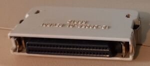
The long inter-enclosure DSSI cables are found with two different types of connectors:
- MR (Micro Ribbon or midrange), with flat contacts = "50 Way High Density Micro Ribbon"
- PS (Pin Socket or pedestal style), with round pins = "50 Way High Density Honda"
With these two different types of connectors, three different types of long DSSI cables are needed:
- MR-MR
- PS-PS
- MR-PS (can be reversed to provide PS-MR)
Two types of DSSI connectors are found on devices:
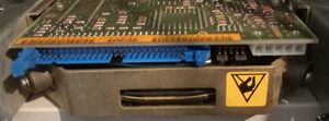
- Single DSSI Device Connector 50-pin (SCSI-like)
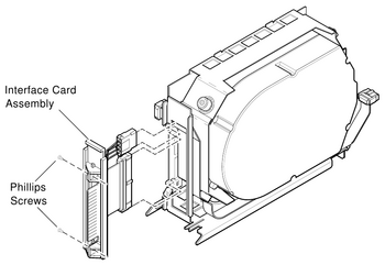
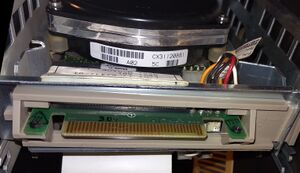
- Dual 3.5" / Single 5.25" DSSI Disk Interface Card Assembly e.g. for VAX 4000, BA430/BA440
DSSI Controllers/Interfaces
- KFQSA QBUS DSSI Adapter
- KFMSA XMI Dual DSSI Adapter
- KFMSB XMI DSSI adapter
- KFESA EISA DSSI Adapter
- KFESB EISA DSSI Adapter
- KFPSA PCI DSSI Adapter
- KFE52 VAXft Multi-Function Interface
- KDXDA VAXft 810 DSSI Interface
- EDA640 MicroVAX 3300/3400 KA640 embedded DSSI Adapter (EDA)
- KFA40 DEC 4000 I/O Module
DSSI Hierarchical Storage Controllers (HSDs)
Hierarchical Storage Controllers:
DSSI Storage Expanders
DSSI Disk Drives
DSSI Tape Drives
Images
External Links
- DSSI - DSSI and related documents at Bitsavers
- Digital's Storage System Interconnect - protocol specification document
- MicroVAX Dual-Host Systems (EK-338AC-DH-003) - contains a clear description of how a DSSI can be used to create a loosely-couple multi-processor
- DSSI VMScluster Installation and Troubleshooting Guide (EK-410AB-MG.D01)
- RF Series Integrated Storage Element User Guide (EK-RF72D-UG-008)
- BA430 BA440 Enclosure Maintenance.pdf (EK-348AB-MG-002)


