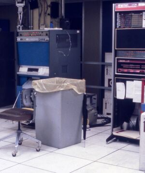
MIT UNIBUS XGP interface
The MIT UNIBUS XGP interface was a one-off UNIBUS peripheral which drove a Xerox Graphics Printer, the earliest raster printer (and thus the ancestor of the ubiquitous laser printer).
It used DMA to transfer rasters from the PDP-11's main memory to the XGP. A raster was 1700. bits long; in the PDP-11 memory, that took 108. words (1728. bits). (Some calculation took the raster length to be 1728. bits.) The raster buffers contained 3 additional words; these apparently were a 2-word header (below), and an "initial image mode word".
"Each [scan] line consists of a header, specifying how long it is, which line it is to be printed upon, and options .. These two words of header are followed by the line in the format required by the XGP interface.
The first PDP-11 word in each line is the number of PDP-11 WORDS .. used for this scan line, including itself and the rest of the header. [The buffer length appears to be in byte-swapped order.] ..
The second PDP-11 word is the scan line upon which this line is to be printed. [It is not clear if this in interpreted by the hardware as well, or just by the driver in the PDP-11.] It is allowable to have non-sequential lines. The unspecified lines will be blank. If the line numbers are not ordered, they will come out as close as possible together, and the internal line count will be reset. .. The top line on a page is numbered 1. ..
Paper cutting may be specified by setting the sign [high bit] of the second PDP-11 word. The rest of the [scan line] so marked will be ignored"
It is not yet clear if this last is interpreted by the hardware, or the driver in the PDP-11.
To print a scan line, load the Memory Address Register (below), set the FGO and FMOT bits in the Control Register (ditto); FDIE as well, to get an interrupt when done. The interface's interrupt vector is 0370.
The XGP at MIT was one of a number provided to various entities by Xerox in 1972; each had to produce its own hardware computer interfaces. MIT connected theirs to a PDP-11/20 (there is some confusion about exactly which model of PDP-11 it was, some think it was PDP-11/05). That was connected to the ITS KA10 MIT-AI via the Rubin 10-11 interface.
Contents
Device registers
| Register | Abbreviation | Address |
|---|---|---|
| Control Register | XCR | 772100 |
| Memory Address Register | XMAR | 772102 |
| Status Register | XSR | 772104 |
| Cut Register | XCUT | 772106 |
772100: Control Register (XCR)
| FERR | Unused | FMOT | Unused | FDONE | FDIE | Unused | FCUTI | FCUT | FGO | ||||||
| 15 | 14 | 13 | 12 | 11 | 10 | 09 | 08 | 07 | 06 | 05 | 04 | 03 | 02 | 01 | 00 |
The header of the driver (below) indicates that FCUTI in in this register, but this is believed to be an error. The code definitely indicates that this bit is in the XCUT register.
772102: Memory Address Register (XMAR)
| BA15 <---> BA01 | Unused | ||||||||||||||
| 15 | 14 | 13 | 12 | 11 | 10 | 09 | 08 | 07 | 06 | 05 | 04 | 03 | 02 | 01 | 00 |
772104: Status Register (XSR)
| FOS | FSYN | FOR | FNXM | FRDYC | FBCB | Unused | Status | FRDY | Status | Unused | FACT | ||||
| 15 | 14 | 13 | 12 | 11 | 10 | 09 | 08 | 07 | 06 | 05 | 04 | 03 | 02 | 01 | 00 |
772106: Control Register (XCUT)
| Unused | FCUTI | Unused | |||||||||||||
| 15 | 14 | 13 | 12 | 11 | 10 | 09 | 08 | 07 | 06 | 05 | 04 | 03 | 02 | 01 | 00 |
Data encoding
The data pointed to by XMAR is DMA'd from memory and decoded by the interface in various modes. For each fresh line, the interface starts off in character mode.
In character mode, the first byte says how many bits of data follow. Subsequent bytes are shifted to the video flip-flop controlling the CRT beam, as many as necessary to reach the bit count. A 0 byte escapes character mode. The next byte decides what mode to switch to: 0 enters vector mode; 1 stops the printer and sets DONE; 2 enters image mode. Anything else is an error.
In vector mode, alternating bytes say how many pixels of white or black to draw. Two zeros in succession escapes back to character mode.
In image mode, bytes are imaged to pixels verbatim. There is no escape except an error condition. Normally this will be an overscan error when the beam reaches the right margin.
External links
- SYSEN2; XGP > - code to run the interface
- INFO; XGP > - documentation on the spooler, and the input file format
- XCRIBL - A Hardcopy Scan Line Graphics System for Document Generation - a fair amount of detail on the CMU system
- Workshop on Hard Copy Line Graphics - details of the XGP installation at CMU
- XGP (Xerox Graphics Printer) in MIT AI Lab - UNIBUS XGP interface (right)
