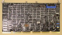
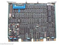
RL11 disk controller
The RL11 disk controllers (the original RL11 for the UNIBUS, and the RLV11 and RLV12 for the QBUS) were for the RL01 and RL02 disk drives. (These drives protect the data, and sector headers, with separate CRCs.)
The RL11 was a hex board, the M7762. The RLV11 consisted of two quad boards, the M8013 and M8014, which used the CD interconnect to communicate; it was program compatible with the RL11. The RLV12 was a single quad board, the M8061; it was mostly program compatible, but added a 'Bus Address Extension' register for use on Q22 systems.
All have a 40-pin Berg connector header holding a flat cable, which runs to a bulkhead-mounted converter from the flat cable to a special inter-drive cable (round in cross-section, with special locking connectors). (If the flat cable is plugged in the wrong way around, nothing is damaged; the drive merely turns on its 'fault' light.)
The cable runs from the converter to the first drive; up to 4 drives can be connected to a single controller, using a bus running from one drive to the next, with a terminator in the last drive of the string.
Contents
Controller capabilities
The controller and drive combination can execute 8 different commands:
- No Operation
- Write Check
- Get Status
- Seek
- Read Header
- Write Data
- Read Data
- Read Data Without Header Check
Implied seeks (i.e. setting the disk address, and then starting a read or write operation, which is intended to happen at that address) are not supported; an explicit seek to the desired cylinder must be performed before the read or write. (This is in part because the Disk Address register is shared between the cylinder move number, during a seek operation, and the starting sector number, during a read or write operation.) Spiral reads and writes (i.e. multi-block reads which start on one track, and overflow to the next) are also not supported; multiple separate read/write commands are needed, with a seek to the next track between each pair.
Device registers
The RL11 controller includes 4 (5 for the RLV12) read-write registers:
| Register | Abbreviation | Address |
|---|---|---|
| Control Status Register | RLCS | 774400 |
| Bus Address Register | RLBA | 774402 |
| Disk Address Register | RLDA | 774404 |
| Multipurpose Register | RLMP | 774406 |
| Bus Address Extension Register RLV12 only |
RLBAE | 774410 |
774400: Control Status Register (RLCS)
| CERR | DE | NXM | DLT/HNF | DCRC/ HCRC | OPI | DRVSEL | CRDY | IE | BUS ADDR EX | FUNC | DRDY | ||||
| 15 | 14 | 13 | 12 | 11 | 10 | 09 | 08 | 07 | 06 | 05 | 04 | 03 | 02 | 01 | 00 |
| Function Code | Function |
|---|---|
| 0 | No Operation |
| 1 | Write Check |
| 2 | Get Status |
| 3 | Seek |
| 4 | Read Header |
| 5 | Write Data |
| 6 | Read Data |
| 7 | Read Data, No Header Check |
OPI - Operation Incomplete
DCRC/HCRC/WCE - Data CRC/Header CRC/Write Check Error
DLT/HNF - Data Late / Header Not Found
DE - Drive Error ('Get Status' will provide details)
CERR - Composite Error
774402: Bus Address Register (RLBA)
| BA15 <---> BA01 | 0 | ||||||||||||||
| 15 | 14 | 13 | 12 | 11 | 10 | 09 | 08 | 07 | 06 | 05 | 04 | 03 | 02 | 01 | 00 |
774404: Disk Address Register (RLDA)
During a 'Seek' command on an RL01:
| 0 | CYL ADDR DIFF | Reserved | HD SEL | 0 | DIR | 0 | 1 | ||||||||
| 15 | 14 | 13 | 12 | 11 | 10 | 09 | 08 | 07 | 06 | 05 | 04 | 03 | 02 | 01 | 00 |
During a 'Seek' command on an RL02:
| CYL ADDR DIFF | Reserved | HD SEL | 0 | DIR | 0 | 1 | |||||||||
| 15 | 14 | 13 | 12 | 11 | 10 | 09 | 08 | 07 | 06 | 05 | 04 | 03 | 02 | 01 | 00 |
During a 'Read Data' or 'Write Data' command on an RL01:
| 0 | CYL ADDR | HD SEL | SECTOR | ||||||||||||
| 15 | 14 | 13 | 12 | 11 | 10 | 09 | 08 | 07 | 06 | 05 | 04 | 03 | 02 | 01 | 00 |
During a 'Read Data' or 'Write Data' command on an RL02:
| CYL ADDR | HD SEL | SECTOR | |||||||||||||
| 15 | 14 | 13 | 12 | 11 | 10 | 09 | 08 | 07 | 06 | 05 | 04 | 03 | 02 | 01 | 00 |
During a 'Get Status' command:
| Unused | MBZ | RESET | 0 | GT STA | 1 | ||||||||||
| 15 | 14 | 13 | 12 | 11 | 10 | 09 | 08 | 07 | 06 | 05 | 04 | 03 | 02 | 01 | 00 |
774406: Multipurpose Register (RLMP)
During a 'Read Data' or 'Write Data' command:
| 111 | WORD COUNT | ||||||||||||||
| 15 | 14 | 13 | 12 | 11 | 10 | 09 | 08 | 07 | 06 | 05 | 04 | 03 | 02 | 01 | 00 |
During a 'Get Status' command:
| WDE | CHE | WL | SKTO | SPE | WGE | VC | DSE | Rsvd | HS | CO | HO | BH | STATE | ||
| 15 | 14 | 13 | 12 | 11 | 10 | 09 | 08 | 07 | 06 | 05 | 04 | 03 | 02 | 01 | 00 |
| State Code | State |
|---|---|
| 0 | Load Cartridge |
| 1 | Spin Up |
| 2 | Brush Cycle |
| 3 | Load Heads |
| 4 | Seek |
| 5 | Lock On |
| 6 | Unload Heads |
| 7 | Spin Down |
During a 'Read Header' command, three successive reads to the Multipurpose Register will return in the first word, on an RL01:
| 0 | CYL ADDR | HD SEL | SECTOR | ||||||||||||
| 15 | 14 | 13 | 12 | 11 | 10 | 09 | 08 | 07 | 06 | 05 | 04 | 03 | 02 | 01 | 00 |
and on an RL02:
| CYL ADDR | HD SEL | SECTOR | |||||||||||||
| 15 | 14 | 13 | 12 | 11 | 10 | 09 | 08 | 07 | 06 | 05 | 04 | 03 | 02 | 01 | 00 |
followed by all 0's in the second word, and the header CRC in the third.
774410: Bus Address Extension Register (RLBAE)
| Unused | BA21 <---> BA16 | ||||||||||||||
| 15 | 14 | 13 | 12 | 11 | 10 | 09 | 08 | 07 | 06 | 05 | 04 | 03 | 02 | 01 | 00 |
Note: This register is present in the RLV12 only.
Bootstraps
This bootstrap (which is position-independent object code, so it can be placed anywhere; 04000 is good) will load the block at sector 0 of cylinder 0 of drive 0 into main memory at address 0:
| Address | Data | Mnemonic | Description |
|---|---|---|---|
| 1000 | 012700 | MOV #174400,R0 | Move the address of the Control Status register into R0 |
| 1002 | 174400 | (constant) | |
| 1004 | 012760 | MOV #177400,6(R0) | Move block size (negative) into Multipurpose register |
| 1006 | 177400 | (constant) | |
| 1010 | 000006 | (constant) | |
| 1012 | 012710 | MOV #14,@R0 | Move 'Read Go' command into CSR |
| 1014 | 000014 | (constant) | |
| 1016 | 105710 | TSTB (R0) | Test for 'Done' bit in CSR |
| 1020 | 100376 | BPL 1016 | Jump backward if not set |
| 1022 | 005007 | CLR PC | Start loaded bootstrap with jump to 0 |
Note that the INIT pulse caused by hitting the front panel's 'Start' button will clear the Bus Address register, so that the loaded block will be placed at location 0; and the Disk Address register, so that sector 0 will be read. If the drive's heads are not on cylinder 0, since a seek on an RL01/02 is relative, a 'Read Header' command would have to be done before a seek could be commanded (or the device driver must remember the current cylinder), and that all would require a fair amount of code. To ensure that the drive is on cylinder 0 for the bootstrap, the drive should be power cycled before starting the bootstrap.
External links
- RL11 Controller Technical Description Manual (EK-0RL11-TD-001)
- RLV11 Controller Technical Description Manual (EK-RLV11-TD-001)
- RLV12 Disk Controller User's Guide (EK-RLV12-UG-002)
- RLV12 Technical Description (EK-RLV12-TD-OOl)
- RL11 Field Maintenance Print Set (MP00153)
- RL11-AK Field Maintenance Print Set (MP00526)
- RLV11 Field Maintenance Print Set (MP00635)
- Field Maintenance Print Set (RLV12) (MP01282)

