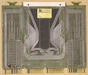
MM11-E and MM1-F core memories
The MM11-E and MM11-F core memories were UNIBUS main memory units; the first UNIBUS memories produced by DEC. They came out with/for the first PDP-11, the PDP-11/20.
They were very similar - both 4K word (8K bytes), and with most of their boards in common. The MM11-F was capable of interleaving (although this capability was then made available to the MM11-E as well); it also had a parity version available, the MM11-FP (which used a 4Kx18 core plane, instead of the 4Kx16 used in the MM11-E and MM11-F).
The MM11-F was also slightly faster: the MM11-E had an access time of 500 nsec and a cycle time of 1.2 μsec; the MM11-F had an access time of 400 nsec and a cycle time of 980 nsec.
Implementation
Both consisted of a quad-width H207 (non-parity) or H210 (parity) core plane board (the H2xx board consisted of a G617 and a G616 Planar Stack boards), along with a number of dual- and single-width cards (all extended-length), plugged into a custom-wired quad system unit backplane. The MM11-F and MM11-FP used the same backplane; only the board set was slightly different.
The MM11-E consisted of:
- H207 core plane (quad)
- M729 Control Logic (dual)
- 4 x G102 Sense Inhibit
- G103 Levels and Gates
- G225 Current Generator
- 4 x G226 Decoder and Switch
- M109 Device Select
The MM11-F consisted of:
- H207 or H210 core plane (quad)
- M7290 Control Logic (dual)
- 4 x G102 Sense Inhibit
- G103 Levels and Gates
- G108 Sense-Inhibit (-FP only)
- G225 Current Generator
- 4 x G226 Decoder and Switch
- M1091 Device Select
So the only major difference is the M7290 Control Logic, instead of the M729.
Board locations
These are the board locations for the MM11-E (as seen from the board side of the backplane):
| Connector | Slot 4 | Slot 3 | Slot 2 | Slot 1 |
|---|---|---|---|---|
| A | UNIBUS Out |
Power | UNIBUS In | |
| B | M109! | |||
| C | H207 | G226 | G226 | M729 |
| D | G102 | G102 | ||
| E | G102 | G102 | G225 | |
| F | G226 | G226 | G103 |
! = Possibly the later M1091: the M1091 could be used in the MM11-E as well as the MM11-F; it appears that later units of the MM11-E shipped with the M1091. The difference between the M109 and M1091 is the addition of additional jumpers to allow interleaving.
These are the board locations for the MM11-F and -FP (as seen from the board side of the backplane):
| Connector | Slot 4 | Slot 3 | Slot 2 | Slot 1 |
|---|---|---|---|---|
| A | UNIBUS Out |
Power | UNIBUS In | |
| B | G225 | M1091 | ||
| C | H207 or H210 |
G226 | G226 | M7290 |
| D | G102 | G102 | ||
| E | G102 | G102 | G108@ | |
| F | G226 | G226 | G103 |
@ = MM11-FP only
External links
- MM11-E Core Memory Manual (DEC-11-HR3A-D) - includes engineering drawings on pp. 24-41
- MM11-F core memory manual (DEC-11-HMFA-D)
- MM11-F core memory manual - scans of individual pages in a tar file
- MM11-F core memory engineering drawings (DEC-11-HMFA-D)
- MM11-F ore memory engineering drawings - scans of individual pages in a tar file
