Difference between revisions of "DLV11-J asynchronous serial line interface"
(+See also, speed, console) |
(+img) |
||
| Line 1: | Line 1: | ||
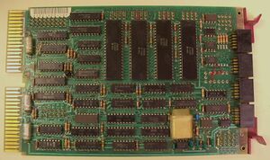
| − | The '''DLV11-J asynchronous serial line interface''' card | + | [[Image:DLV11-J.jpg|thumb|right|300px|DLV11-J M8043 board]] |
| + | |||
| + | The '''DLV11-J asynchronous serial line interface''' card was a [[QBUS]] [[peripheral]] for the [[PDP-11]] series of computers which provided four [[asynchronous serial line]]s on a single [[DEC card form factor|dual-width]] card, the N8043. | ||
It provided both [[EIA RS-232 serial line interface|EIA RS-232]] or [[EIA RS-422 serial line interface|RS-422]] connectivity at speeds of 150 to 38.4K [[baud rate|baud]]; receive and transmit speeds are the same on each line, but each line could be set independently. It did not have any [[modem]] control. | It provided both [[EIA RS-232 serial line interface|EIA RS-232]] or [[EIA RS-422 serial line interface|RS-422]] connectivity at speeds of 150 to 38.4K [[baud rate|baud]]; receive and transmit speeds are the same on each line, but each line could be set independently. It did not have any [[modem]] control. | ||
| − | Line connection was via 10-pin [[Berg connector]] headers on the top edge of the card, using the standard [[DEC asynchronous serial line pinout]]. | + | Line connection was via four separate 10-pin [[Berg connector]] headers on the top edge of the card, using the standard [[DEC asynchronous serial line pinout]]. |
==Programing interface== | ==Programing interface== | ||
| − | Like the ancestral [[KL11 asynchronous serial line interface|KL11]], for each line the DL11-J has 2 device [[register]]s for the receive side (one Control and Status Register - CSR - and one data [[buffer]] register), and similarly, two for the transmit side. Each line has two [[interrupt vector]]s - again, one receive, and one transmit. | + | Like the ancestral [[KL11 asynchronous serial line interface|KL11]], for each line the DL11-J has 2 device [[register]]s for the receive side (one Control and Status Register - CSR - and one data [[buffer]] register), and similarly, two for the transmit side. Each line has two [[interrupt vector]]s - again, one receive, and one transmit. The DLV11-J is [[program compatible]] with other KL11-type interfaces. |
Normally both the registers and interrupt vectors are in contiguous blocks for the 4 lines, but there are special provisions for one line to be configured as the PDP-11 main console (which is always a KL11/DL11 compatible device). The standard there is that 0777560 is the base address (so the receiver registers are 0777560-2, and the transmitter are 0777564-6), and 060 is the base vector. | Normally both the registers and interrupt vectors are in contiguous blocks for the 4 lines, but there are special provisions for one line to be configured as the PDP-11 main console (which is always a KL11/DL11 compatible device). The standard there is that 0777560 is the base address (so the receiver registers are 0777560-2, and the transmitter are 0777564-6), and 060 is the base vector. | ||
Revision as of 22:22, 21 September 2020
The DLV11-J asynchronous serial line interface card was a QBUS peripheral for the PDP-11 series of computers which provided four asynchronous serial lines on a single dual-width card, the N8043.
It provided both EIA RS-232 or RS-422 connectivity at speeds of 150 to 38.4K baud; receive and transmit speeds are the same on each line, but each line could be set independently. It did not have any modem control.
Line connection was via four separate 10-pin Berg connector headers on the top edge of the card, using the standard DEC asynchronous serial line pinout.
Programing interface
Like the ancestral KL11, for each line the DL11-J has 2 device registers for the receive side (one Control and Status Register - CSR - and one data buffer register), and similarly, two for the transmit side. Each line has two interrupt vectors - again, one receive, and one transmit. The DLV11-J is program compatible with other KL11-type interfaces.
Normally both the registers and interrupt vectors are in contiguous blocks for the 4 lines, but there are special provisions for one line to be configured as the PDP-11 main console (which is always a KL11/DL11 compatible device). The standard there is that 0777560 is the base address (so the receiver registers are 0777560-2, and the transmitter are 0777564-6), and 060 is the base vector.
That line can be set to halt the CPU, or re-boot the system, when a 'break' is seen. All lines can send a 'break'.
The first line after the console is always assigned the address 0776500, and vector 0300. Additional lines are assigned addresses and vectors immediately following, for DL11's #1-#16 (i.e. 0776500-676 and 0300-0476).
