Difference between revisions of "Talk:Incompatible Timesharing System"
m (→AI configuration) |
(→AI configuration: I get the MIT DF10 functionality; it's the details of how the bus works I'm after) |
||
| Line 110: | Line 110: | ||
:: HW memo 2 documents the AI pager: https://github.com/larsbrinkhoff/its-archives/blob/master/ailab/ITS_Hardware_Memo_2.pdf | :: HW memo 2 documents the AI pager: https://github.com/larsbrinkhoff/its-archives/blob/master/ailab/ITS_Hardware_Memo_2.pdf | ||
:: [[User:Larsbrinkhoff|Larsbrinkhoff]] ([[User talk:Larsbrinkhoff|talk]]) 16:05, 14 April 2021 (CEST) | :: [[User:Larsbrinkhoff|Larsbrinkhoff]] ([[User talk:Larsbrinkhoff|talk]]) 16:05, 14 April 2021 (CEST) | ||
| + | |||
| + | : I know about the ''functionality'' of the MIT DF10, which is actually already [[DF10|described here]]. I'm trying to work out the ''low-level details'' of how the cabling, etc, actually worked. According to e.g. the [http://www.bitsavers.org/pdf/dec/pdp10/KA10/DEC-10-HIFB-D_InterfaceManual_May68.pdf PDP-10 Interface Manua] (DEC-10-HIFB-D), Chapter 7, the KA10 memory bus has only 18 bits of address. So if one has 512KW of memory ... how does one address it? I had a theory that maybe there was a separate 18-bit-address bus for each moby, but of course there are other possibilities. I'm not sure if the connector (pg. 124) has any spare pins; if so, they could be used - but would need an extra wire run from one end of the cable to the other. A better possibility is that a number of signals (A18-A22, A35) are present in positive and negative logic forms, and maybe one of the semi-duplicates could be disposed of, and the pin re-used for, say, A17. | ||
| + | : I'm about to email Jack Haverty, to ask him about DM's memory configuration; I'll ask him, maybe he knows. If not, we can ask RG, he should know. [[User:Jnc|Jnc]] ([[User talk:Jnc|talk]]) 20:41, 14 April 2021 (CEST) | ||
Revision as of 20:41, 14 April 2021
Contents
AI PDP-6
I'm pretty sure that by the time I got to Tech Sq (in 1977), the PDP-6 was no longer in use. It wasn't physically removed until some years later, though. Jnc (talk) 15:43, 14 December 2017 (CET)
- Right. I have collected all information I have found on each of the classical ITS machines here: [1], but I figured it was too much for this page. User:Larsbrinkhoff 18:14, 14 December 2017 (CET)
Timeline
Comment on "after Multics was done". I believe both Multics and ITS were developed around the same time. User:Larsbrinkhoff 11:11, 15 December 2017 (CET)
- Well, the planning for Multics I believe started first; 1964 or so (the timeline on the Multicians site doesn't give the exact date, but they selected GE in 1964, so it was certainly underway then). The first boot of a Multics came in December '67. As for ITS, the AI Lab history, "A Marriage of Convenience: The Founding of the MIT Artificial Intelligence Laboratory" implies that it was started, and finished, sometime in '67, on a PDP-6 already owned by the Lab, but no specific date is given. Jnc (talk) 14:49, 15 December 2017 (CET)
- It seems right that Multics implementation started well before that of ITS. But they become operational at about the same time; actually ITS was first. Project MAC Progress Report IV has this to say: "A time-sharing system for the PDP-6 went into operation in July 1967." User:Larsbrinkhoff 15:31, 15 December 2017 (CET)
PCLSRing
I found this posted to alt.sys.pdp10: "The [TENEX] exception model for system calls was as ugly as their hardware, instead of adopting an ITS-like PCLSR approach - another step backwards from the 940 system, which in essence had simplified PCLSR." Larsbrinkhoff (talk)
MC configuration
So I'm trying to work out MC's configuration. (I know, I know, I could look in CONFIG >, but I'm lazy.) Here's what I remember/can work out:
- 8 MF10's
- (later) An Ampex? 'external' memory box was added
- 3 RP04's
- So, therefore, some sort of MASSBUS controller, but since it was a KL10 Model A, not an RH20; probably an RH10
- That would have needed a DF10
- A TM10 of some sort; dunno if that had a separate DF10, or shared the one the RH10 used
- Some sort of high-end DEC magtape drive
- A DL10
- Later, first one, and then a second Trident drive, attached to the DL10 PDP-11
- The front-end -11 had a bunch of serial lines, probably a DH11
- CHAOSNET eventually on the DL10 PDP-11
- I'm not sure why they initially acquired the DL10+PDP-11 (i.e. what it did to begin with); probably more serial lines
Well, that's a start. Jnc (talk) 17:09, 12 April 2021 (CEST)
- According to SYSDOC;POOR MC, the tape drive was a TU40 or TU41 (probably TU40). Also, it seems from things said there that it did have its own DF10. Jnc (talk) 17:20, 13 April 2021 (CEST)
- I have tried to summarize changes to CONFIG > for all machines over the years: https://github.com/PDP-10/its/issues/1168
- Most of what you wrote seems spot on. I can see there was a third T-300. Yes, initially the DL10 front end was just a normal DC76 handling terminals. Larsbrinkhoff (talk) 17:29, 12 April 2021 (CEST)
- Where is CONFIG > now? I looked here: https://github.com/PDP-10/its/tree/master/src/system here but it doesn't seem to be there. Jnc (talk) 17:47, 12 April 2021 (CEST)
- Many (all maybe?) versions are here: https://github.com/PDP-10/its-vault/tree/master/files/system/ Larsbrinkhoff (talk) 17:51, 12 April 2021 (CEST)
- Ah, thanks.
- It looks like it doesn't say what kind of tape drive it was; it was a TU77, or something. If we ever get good photos of the machine, we should be able to tell (also, if there was a second DF10).
- I wonder why they did the whole DL10 thing just to get a few more serial lines. Maybe the DTE20 one was maxed out?
- I see from the IOELEV/KLDCP source that the DTE20 -11 had a TU56; I vaguely remember that. Jnc (talk) 18:53, 12 April 2021 (CEST)
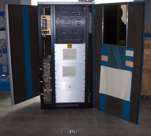
- I only know of one photo of MC when at MIT, the one on the ITS page, but there's no tape drive. I saw MC in LCM storage, but I don't remember any peripherals. Larsbrinkhoff (talk) 18:59, 12 April 2021 (CEST)
- Here is the layout of the machine, as best as I can remember it. The tape drive would not have been in the field of that image.
- A couple of notes. I'm sure of the CPU, MF10's,
FabridrekAmpex, RP04's, Tape, Trident and DL10 locations. The RH10/DF10 were I think in that corner, but I'm not positive, and I don't remember which order. Ditto for the order of the DL10 and its PDP-11 (which I think was an 11/40). I think the TM10 was there somewhere, but I'm kind of guessing; I don't think it was next to the drive, but it might have been. Jnc (talk) 20:34, 12 April 2021 (CEST)
- Ah, looking at that image, it's taken from just in front of the Ampex; you can see a corner of it. The RH10/DF10 are indeed in that corner; you can also see a bit of the RP04's behind them. The tape drive would be behind the camera; too bad we don't have a shot in that direction. Jnc (talk) 21:51, 12 April 2021 (CEST)
Very interesting, thanks! I suggest copying your comment to File_talk:Mit-mc.jpg. Larsbrinkhoff (talk) 20:58, 12 April 2021 (CEST)
- Probably Talk:Incompatible Timesharing System would be better. I'll move the whole thread there. Jnc (talk) 21:51, 12 April 2021 (CEST)
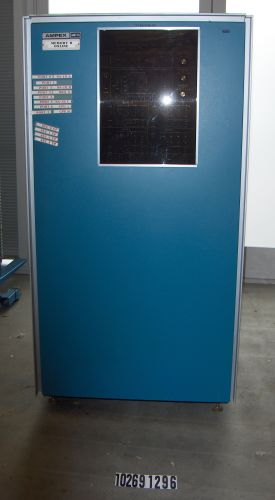
I wish we could confirm what the new memory was; it was probably an Ampex ARM10, since other KL10's are reported to have had those (e.g. Guy S's machine); maybe some mail log file, or Moon's ITS changes log file, will mention it. Ah, there's an image of one the CHM has/had here (inside here), and that is indeed what was added to MC. (Well, I don't remember the inside well, but the outside matches.)
Every so often a module (CHM image here; they were huge, physically) would fail, and we'd have to take the machine out of 4-way interleave; same thing when an MF10 failed. Jnc (talk) 14:05, 13 April 2021 (CEST)
- Also, in SYSDOC;POOR MC, MOON (who knew more about MC than any other human) refers to "MH10 C". So maybe my memory flaked (again, sigh) and they're actually MH10's, not MF10's. Jnc (talk) 17:20, 13 April 2021 (CEST)
- But SYSDOC;KL10 FLKLOR refers to MF10's. So maybe they were upgraded at some point? Jnc (talk) 17:32, 13 April 2021 (CEST)
- There is a lot about failing Ampex ARM10 modules in Moon's files, so I would assume that confirms your recollection. I don't have any good, clear information about which ITS machines had what kind of memory, but Ampex is generally mentioned a lot. Given a lot of time, one could probably dig out an uneven coverage of part numbers, serial numbers, prices, dates, etc. Larsbrinkhoff (talk) 14:29, 13 April 2021 (CEST)
DM/ML configuration
It shouldn't be too hard to figure out DM and ML's configuration; between my (and if needed, other people's) memory, CONFIG >, and similar sources.
Both had RP10's with a DF10. ML had RP03's (I think; definitely RP0x's), but I forget how many; DM I vaguely recall also had DEC disks. I recall that ML's had a slanted top front panel, which I think made them RP03's; those on DM had vertical panels, I think, which I think were RP02's. Per SYSDOC; POOR MC, both DM and ML (and also AI) had TU20 tape drives; one had a TM10A (no DF10, just an I/O bus connection), and one a TM10B (with DF10, but I don't know if the DF10 was shared with the RP10, or a separate one - a DF10 could be shared between several controllers); CONFIG > reveals that it was DM that had the DMA one.
For main memory, ML I think had 4 MD10s, @128KW each. DM I'm pretty sure had 2 MD10's, and a collection of other DEC early memory boxes (MA10's and/or MB10's) totalling 256KW. I can ask Jack Haverty (and old DM hacker) if he remembers the details. Tim Anderson might remember too. Both machines has Systems Concepts DM-10 mapping boxes, of course.
So that's a good start. Jnc (talk) 02:32, 14 April 2021 (CEST)
- CONFIG says RP02 for both DM and ML, but ITS, SALV, and DSKDMP checks the type at run time and supports both RP02 and RP03.
- I think the DF10 was shared between the disk and tape. This configuration is used with the KA10 emulator running ITS.
- The KA10 DF10s had a special hack to make them work with 20-bit physical addresses.
- I have collected some notes about the evolving memory configurations: https://github.com/PDP-10/its/issues/1585
- Two diagrams of DM. Neither has a tape drive.
- https://github.com/PDP-10/its/issues/181#issuecomment-483222759
- https://github.com/PDP-10/its/issues/181#issuecomment-489417548
- Larsbrinkhoff (talk) 08:21, 14 April 2021 (CEST)
- [2] says DM had 3x RP02's and 3x RP03's; that sounds about right. CONFIG says ML had 7 drives, which sounds a bit high, but I suppose could (must?) be right. Ah, SHUT DOWN says it has 4 DEC disks and 4 (2 bays, 2-high) CalChomps (just like the ones on AI); that rings a bell, I recall the CalChomps now. (That memo also confirms DM's disks.)
- DM definitely had a tape drive; CONFIG confirms that.
- I think we're mostly done with these two now (although I have ignored the serial line controller(s) for now). Jnc (talk) 15:36, 14 April 2021 (CEST)
AI configuration
There was a long list of "fanciful hardware" (i.e. kludges) attached to the AI PDP-10.
For now, I'll point to Hardware memo 3 which says there was the 256K moby, plus a DEC 16K and an Ampex 16K. It seems one of those 16K memories would later go somewhere else.
- When I was around, the smaller memories were powered off, and later flushed. The machine had 512KW: the 256KW Fabridrek moby, and another 256KW unit, about which I have been racking my brains all evening trying to remember, and can't quite. Later they both (I think) went away, and HIC added the memory box that used CADR memory boards.
- One thing I'm curious about was how the memory bus worked, for more than 256KW (the vanilla KA memory bus only supported 256KW). I had assumed that the mapping box produced separate memory busses for each moby, so standard cables could be used, and the memories remain un-altered. The flaw in this theory is the DF10's; I suppose they could have been modified to use the same kludge, but...? Maybe ask RG? (He's know about the memory too.) Jnc (talk) 15:36, 14 April 2021 (CEST)
- Note that AI didn't have a DF10; Systems Concepts' DC10 and DK10 had DMA access, and TM10A was IO bus only.
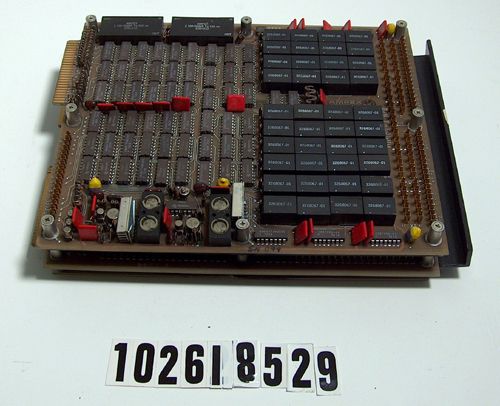
- The DF10s were indeed modified: "MIT-ML and MIT-DM (also KA's) had 18-bit DF10's with a special kludge modification (disabled with a toggle switch for running DEC diagnostics) to take extra address bits from the complement of some high-order bits of the count. The complementation is so that with a small count (which is negative) you address the low-order memory, for compatibility." (David Moon, 1985, KS-ITS mailing list)
- HW memo 2 documents the AI pager: https://github.com/larsbrinkhoff/its-archives/blob/master/ailab/ITS_Hardware_Memo_2.pdf
- Larsbrinkhoff (talk) 16:05, 14 April 2021 (CEST)
- I know about the functionality of the MIT DF10, which is actually already described here. I'm trying to work out the low-level details of how the cabling, etc, actually worked. According to e.g. the PDP-10 Interface Manua (DEC-10-HIFB-D), Chapter 7, the KA10 memory bus has only 18 bits of address. So if one has 512KW of memory ... how does one address it? I had a theory that maybe there was a separate 18-bit-address bus for each moby, but of course there are other possibilities. I'm not sure if the connector (pg. 124) has any spare pins; if so, they could be used - but would need an extra wire run from one end of the cable to the other. A better possibility is that a number of signals (A18-A22, A35) are present in positive and negative logic forms, and maybe one of the semi-duplicates could be disposed of, and the pin re-used for, say, A17.
- I'm about to email Jack Haverty, to ask him about DM's memory configuration; I'll ask him, maybe he knows. If not, we can ask RG, he should know. Jnc (talk) 20:41, 14 April 2021 (CEST)