Difference between revisions of "DMA20 Memory Bus Adapter"
m (→External links: +Eng drw) |
(Bandwidth as well as interleaving) |
||
| (3 intermediate revisions by the same user not shown) | |||
| Line 1: | Line 1: | ||
| − | The '''DMA20 Memory Bus Adapter''' is an optional [[device controller|controller]] on [[KL10]] [[Central Processing Unit|CPUs]] which converts from the KL10's native SBus [[main memory]] [[bus]] to | + | The '''DMA20 Memory Bus Adapter''' is an optional [[device controller|controller]] on [[KL10]] [[Central Processing Unit|CPUs]] which converts from the KL10's native [[PDP-10 Memory Bus|SBus]] [[main memory]] [[bus]] to up to 4 old-style [[PDP-10 Memory Bus]]ses (termed 'KBus' here), to allow existing [[PDP-10]] [[core memory|core]] main memory to be used on one. (In a [[multi-processor]] system, each CPU has a separate DMA20, if configured to have one; the [[multi-port memory]] banks of [[PDP-10 memories]] will allow banks to be shared between CPUs.) |
==Implementation== | ==Implementation== | ||
| Line 5: | Line 5: | ||
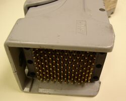
[[Image:KBusQCLatched.jpg|250px|thumb|right|Memory bus Quick Latch connector (in latched position)]] | [[Image:KBusQCLatched.jpg|250px|thumb|right|Memory bus Quick Latch connector (in latched position)]] | ||
| − | The DMA20 is connected to the MBox of the KL10 via the SBus. | + | The DMA20 is connected to the MBox of the KL10 via the SBus. As mentioned, it provides four separate KBuses per CPU, to increase memory bandwidth, as well allow maximum [[memory interleaving|interleaving]]; the DMA20 can operate in 1-, 2- or 4-bus mode. |
It consists of ten [[DEC card form factor|hex]] boards (an M8560, M8563, and eight M8558 modules) plugged into an I/O [[backplane]] (one shared with the [[DIA20 IBus Adapter]]) of the KL10; these are connected to memory bus connectors mounted lower down in that rack. | It consists of ten [[DEC card form factor|hex]] boards (an M8560, M8563, and eight M8558 modules) plugged into an I/O [[backplane]] (one shared with the [[DIA20 IBus Adapter]]) of the KL10; these are connected to memory bus connectors mounted lower down in that rack. | ||
Latest revision as of 13:10, 9 November 2023
The DMA20 Memory Bus Adapter is an optional controller on KL10 CPUs which converts from the KL10's native SBus main memory bus to up to 4 old-style PDP-10 Memory Busses (termed 'KBus' here), to allow existing PDP-10 core main memory to be used on one. (In a multi-processor system, each CPU has a separate DMA20, if configured to have one; the multi-port memory banks of PDP-10 memories will allow banks to be shared between CPUs.)
Implementation
The DMA20 is connected to the MBox of the KL10 via the SBus. As mentioned, it provides four separate KBuses per CPU, to increase memory bandwidth, as well allow maximum interleaving; the DMA20 can operate in 1-, 2- or 4-bus mode.
It consists of ten hex boards (an M8560, M8563, and eight M8558 modules) plugged into an I/O backplane (one shared with the DIA20 IBus Adapter) of the KL10; these are connected to memory bus connectors mounted lower down in that rack.
External links
- DMA20 Memory Bus Adapter Unit Description
- KL10-PV Field Maintenance Print Set - Contains DMA20 on pp. 488-529
- KL10-Based Physical Description - contains images of DMA20 backplanes and wiring, pp. 3-7-3-11; board configuration, pp. 3-27,3-28
