Difference between revisions of "Knight TV system"
(A good start) |
m (→External links: typo) |
||
| (4 intermediate revisions by the same user not shown) | |||
| Line 1: | Line 1: | ||
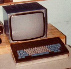
| + | [[Image:KnightTVStationCrop.jpg|250px|thumb|right|Knight TV station]] | ||
| + | |||
The '''Knight TV system''' was one of the very first [[bit-mapped display]] systems. It consisted of two [[UNIBUS]] [[device]]s, built onto a [[PDP-11/10]] (the 'TV-11'), which was connected to the MIT-AI [[time-sharing]] [[KA10]] system, through the [[Rubin 10-11 interface]] to the [[PDP-10]]. | The '''Knight TV system''' was one of the very first [[bit-mapped display]] systems. It consisted of two [[UNIBUS]] [[device]]s, built onto a [[PDP-11/10]] (the 'TV-11'), which was connected to the MIT-AI [[time-sharing]] [[KA10]] system, through the [[Rubin 10-11 interface]] to the [[PDP-10]]. | ||
One was the bit-mapped display unit, which contained a large amount of [[Dynamic RAM|DRAM]] (using the then-new [[Intel 1103]] [[integrated circuit|chips]]), enough to provide 16 independent [[frame buffer]]s. The outputs from these were run into a [[video switch]], which could drive up to 63 stations (about 30 were actually installed, on the 3rd, 8th and 9th floors of the [[Technology Square]] building), each consisting of a relatively square [[cathode ray tube|CRT]] ([[resolution]] 576x454 [[pixel]]s) [[display]]s. Associated with each display was a [[keyboard]]; these were all connected to the other device in the system, a keyboard [[multiplexer]]. | One was the bit-mapped display unit, which contained a large amount of [[Dynamic RAM|DRAM]] (using the then-new [[Intel 1103]] [[integrated circuit|chips]]), enough to provide 16 independent [[frame buffer]]s. The outputs from these were run into a [[video switch]], which could drive up to 63 stations (about 30 were actually installed, on the 3rd, 8th and 9th floors of the [[Technology Square]] building), each consisting of a relatively square [[cathode ray tube|CRT]] ([[resolution]] 576x454 [[pixel]]s) [[display]]s. Associated with each display was a [[keyboard]]; these were all connected to the other device in the system, a keyboard [[multiplexer]]. | ||
| + | |||
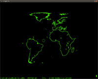
| + | [[Image:KnightTVWorld.png|200px|thumb|left|Display of a world map on a simulated Knight TV display]] | ||
The code running in the PDP-11 read keystrokes, and fed them to the PDP-10. The PDP-10 could either send text to the TV-11, which wrote the appropriate pixels into the frame buffers to display it; alternatively a frame buffer could be mapped into the [[address space]] of a [[process]] on the [[Incompatible Timesharing System|ITS]] machine, which could then write directly into the hardware frame buffer. | The code running in the PDP-11 read keystrokes, and fed them to the PDP-10. The PDP-10 could either send text to the TV-11, which wrote the appropriate pixels into the frame buffers to display it; alternatively a frame buffer could be mapped into the [[address space]] of a [[process]] on the [[Incompatible Timesharing System|ITS]] machine, which could then write directly into the hardware frame buffer. | ||
| + | |||
| + | This may all seem commonplace to modern computer users (i.e. essentially everyone), but it was a revelation to computer professionals at the time; no other contemporary display technology, not even [[vector graphics]] displays, could produce the kind of detail seen in images such as the world map (to the left; the simulation is a very good approximation of what a contemporary user would have seen on an actual Knight TV display). | ||
| + | |||
| + | ==See also== | ||
| + | |||
| + | * [[:Image:KnightTVKeyboard.jpg|Actual Knight TV keyboard]] | ||
| + | * [[:Image:Knight-keyboard.png|Simulated Knight TV keyboard]] | ||
==External links== | ==External links== | ||
| + | * [https://github.com/PDP-10/its/blob/master/doc/sysdoc/tv.100 TV 100] - user documentation | ||
* [https://github.com/PDP-10/its/blob/master/src/system/tv.147 TV 147] - source for the PDP-11 code | * [https://github.com/PDP-10/its/blob/master/src/system/tv.147 TV 147] - source for the PDP-11 code | ||
* [https://www.computerhistory.org/collections/catalog/102803892 Knight TV Controller] - perhaps the only image of the hardware left | * [https://www.computerhistory.org/collections/catalog/102803892 Knight TV Controller] - perhaps the only image of the hardware left | ||
* [http://pdp-6.net/knight-tv/knight-tv.html Knight TV resurrection] | * [http://pdp-6.net/knight-tv/knight-tv.html Knight TV resurrection] | ||
* [https://github.com/PDP-10/its/wiki/Knight-TV-and-keyboard Knight TV and keyboard] | * [https://github.com/PDP-10/its/wiki/Knight-TV-and-keyboard Knight TV and keyboard] | ||
| + | * [https://github.com/PDP-10/its-vault/blob/master/files/tvhare/tvhare.632 TVHARE 632] - "a package of lisp functions" to manipulate HAREs on a Knight TV display; source has some comments that talk about the interface from the PDP-10 side | ||
| + | ** [https://github.com/PDP-10/its-vault/blob/master/files/tvhare/hardoc.464 HARDOC 464] - user documentation | ||
* [[MIT]] Knight TV videos: | * [[MIT]] Knight TV videos: | ||
** [http://projects.csail.mit.edu/video/history/aifilms/x05-graphics.mp4 GRAPHICS bkph] | ** [http://projects.csail.mit.edu/video/history/aifilms/x05-graphics.mp4 GRAPHICS bkph] | ||
Latest revision as of 18:06, 20 March 2024
The Knight TV system was one of the very first bit-mapped display systems. It consisted of two UNIBUS devices, built onto a PDP-11/10 (the 'TV-11'), which was connected to the MIT-AI time-sharing KA10 system, through the Rubin 10-11 interface to the PDP-10.
One was the bit-mapped display unit, which contained a large amount of DRAM (using the then-new Intel 1103 chips), enough to provide 16 independent frame buffers. The outputs from these were run into a video switch, which could drive up to 63 stations (about 30 were actually installed, on the 3rd, 8th and 9th floors of the Technology Square building), each consisting of a relatively square CRT (resolution 576x454 pixels) displays. Associated with each display was a keyboard; these were all connected to the other device in the system, a keyboard multiplexer.
The code running in the PDP-11 read keystrokes, and fed them to the PDP-10. The PDP-10 could either send text to the TV-11, which wrote the appropriate pixels into the frame buffers to display it; alternatively a frame buffer could be mapped into the address space of a process on the ITS machine, which could then write directly into the hardware frame buffer.
This may all seem commonplace to modern computer users (i.e. essentially everyone), but it was a revelation to computer professionals at the time; no other contemporary display technology, not even vector graphics displays, could produce the kind of detail seen in images such as the world map (to the left; the simulation is a very good approximation of what a contemporary user would have seen on an actual Knight TV display).
See also
External links
- TV 100 - user documentation
- TV 147 - source for the PDP-11 code
- Knight TV Controller - perhaps the only image of the hardware left
- Knight TV resurrection
- Knight TV and keyboard
- TVHARE 632 - "a package of lisp functions" to manipulate HAREs on a Knight TV display; source has some comments that talk about the interface from the PDP-10 side
- HARDOC 464 - user documentation
- MIT Knight TV videos:

