Difference between revisions of "MS11 Semiconductor Memory System"
(Minor tweaks) |
m (Better category) |
||
| (9 intermediate revisions by the same user not shown) | |||
| Line 1: | Line 1: | ||
| + | [[Image:MS11M8120Controller.jpg|thumb|300px|right|An M8120 MS11 controller card]] | ||
| + | |||
The '''MS11 Semiconductor Memory Systems''' were a set of special high-speed memories for the [[PDP-11/45]], which plugged into special dedicated, pre-wired slots in the [[backplane]] of the the [[KB11-A CPU|KB11-A]] and [[KB11-D CPU]]. | The '''MS11 Semiconductor Memory Systems''' were a set of special high-speed memories for the [[PDP-11/45]], which plugged into special dedicated, pre-wired slots in the [[backplane]] of the the [[KB11-A CPU|KB11-A]] and [[KB11-D CPU]]. | ||
| Line 8: | Line 10: | ||
In all versions, each bank included a controller board, and up to 4 storage boards; all cards were [[DEC card form factor|hex]] size. Each bank had to be all MOS or all bipolar (one size); however, there could be one bipolar bank and one MOS bank. | In all versions, each bank included a controller board, and up to 4 storage boards; all cards were [[DEC card form factor|hex]] size. Each bank had to be all MOS or all bipolar (one size); however, there could be one bipolar bank and one MOS bank. | ||
| + | |||
| + | ==Parity== | ||
The storage boards were available in both non-[[parity]] and parity versions (except the larger bipolar ones, which were available in parity only), the latter being indicated by a trailing '-YA' on the board number. | The storage boards were available in both non-[[parity]] and parity versions (except the larger bipolar ones, which were available in parity only), the latter being indicated by a trailing '-YA' on the board number. | ||
| + | |||
| + | Information on the parity control [[register]]s can be found in the ''pdp-11/45 processsor handbook'' (1972 and 1973 editions) where a little-known "Appendix E: Memory Parity", referred to in "2.5.6 Memory Parity", indicates that there are "16 memory status registers ... each one associated with an 8K section of memory". | ||
| + | |||
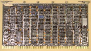
| + | These sound from the writeup like they are in the KB11-A CPU, but in fact they are in the MS11 controller board. | ||
| + | |||
| + | They can control, for each 4k block of that section, whether the memory uses odd or even parity, whether parity is enabled for that section, and whether a parity error will cause the machine to [[halt]] or [[trap]]. | ||
==MS11-B MOS== | ==MS11-B MOS== | ||
| Line 29: | Line 39: | ||
* MS11-CM, -CP 1K Bipolar Memory Matrix (M8111) | * MS11-CM, -CP 1K Bipolar Memory Matrix (M8111) | ||
| − | The M8110 was later replaced by the M8120, which used the same [[printed circuit board]], but with (as yet un-determined) component variations. The -CM and -CP are the nomenclature for the non-parity and parity versions. | + | The M8110 was later replaced by the M8120, which used the same [[printed circuit board]], but with (as yet un-determined) component variations and/or [[Engineering Change Order|ECOs]]; the later manuals make it sound as if the bipolar will only work with an M8120, but the early manuals make it clear that an M8110 is acceptable. The -CM and -CP are the nomenclature for the non-parity and parity versions. |
==MS11-A Bipolar== | ==MS11-A Bipolar== | ||
| − | The MS11- | + | [[Image:MS11-AP.jpg|thumb|300px|left|An MS11-AP storage card]] |
| + | |||
| + | The MS11-A consisted of: | ||
* MS11-CC Bipolar Memory Control (M8120) | * MS11-CC Bipolar Memory Control (M8120) | ||
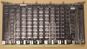
* MS11-AP 4K Bipolar Memory Matrix (M8121) | * MS11-AP 4K Bipolar Memory Matrix (M8121) | ||
| − | + | [[Category: PDP-11 Memories]] | |
| − | |||
| − | [[Category: PDP-11]] | ||
Latest revision as of 01:21, 6 February 2024
The MS11 Semiconductor Memory Systems were a set of special high-speed memories for the PDP-11/45, which plugged into special dedicated, pre-wired slots in the backplane of the the KB11-A and KB11-D CPU.
The MS11 was dual-ported memory, with one port connected to the separate 'B' UNIBUS of the PDP-11/45, and the other to the CPU through a special bus, the Fastbus. A PDP-11/45 could have up to two separate MS11 banks.
There were three different versions: initially the MS11-B MOS (450 nsec) and MS11-C bipolar memory (300 nsec); and later the MS11-A larger, but otherwise identical, bipolar memory.
Any version could be added to a stock PDP-11/45, but DEC sold versions of that machine pre-configured with MOS or bipolar as the PDP-11/50 and PDP-11/55, respectively.
In all versions, each bank included a controller board, and up to 4 storage boards; all cards were hex size. Each bank had to be all MOS or all bipolar (one size); however, there could be one bipolar bank and one MOS bank.
Parity
The storage boards were available in both non-parity and parity versions (except the larger bipolar ones, which were available in parity only), the latter being indicated by a trailing '-YA' on the board number.
Information on the parity control registers can be found in the pdp-11/45 processsor handbook (1972 and 1973 editions) where a little-known "Appendix E: Memory Parity", referred to in "2.5.6 Memory Parity", indicates that there are "16 memory status registers ... each one associated with an 8K section of memory".
These sound from the writeup like they are in the KB11-A CPU, but in fact they are in the MS11 controller board.
They can control, for each 4k block of that section, whether the memory uses odd or even parity, whether parity is enabled for that section, and whether a parity error will cause the machine to halt or trap.
MS11-B MOS
The MS11-B consisted of:
- MS11-BC or -BD MOS Memory Control (M8110)
- MS11-BM, -BP, -BR and -BT 4K MOS Memory Matrix (G401)
In addition, the MS11-B required the special H746 MOS Regulator power supply module, which produced the special voltages needed by this memory.
The -BC and -BD variants are DEC nomenclature for the first and second controllers, both being packaged with an H746, but only the former also included the needed extra H744. The -BM and -BP are the nomenclature for the non-parity and parity versions.
MS11-C Bipolar
The MS11-C consisted of:
- MS11-CC Bipolar Memory Control (M8110)
- MS11-CM, -CP 1K Bipolar Memory Matrix (M8111)
The M8110 was later replaced by the M8120, which used the same printed circuit board, but with (as yet un-determined) component variations and/or ECOs; the later manuals make it sound as if the bipolar will only work with an M8120, but the early manuals make it clear that an M8110 is acceptable. The -CM and -CP are the nomenclature for the non-parity and parity versions.
MS11-A Bipolar
The MS11-A consisted of:
- MS11-CC Bipolar Memory Control (M8120)
- MS11-AP 4K Bipolar Memory Matrix (M8121)

