Difference between revisions of "PDP-10 Memory Bus"
m (→See also: +PDP-10 I/O Bus) |
m (→External links: +decsystem-1080/1090 System Description) |
||
| (3 intermediate revisions by the same user not shown) | |||
| Line 5: | Line 5: | ||
The first two were the so-called 'external memory bus', in KA (18-bit [[address]]) and KI (22-bit) forms (for the [[KA10]], and [[KI10]] and early [[KL10]], respectively), although they also had minor [[protocol]] differences. | The first two were the so-called 'external memory bus', in KA (18-bit [[address]]) and KI (22-bit) forms (for the [[KA10]], and [[KI10]] and early [[KL10]], respectively), although they also had minor [[protocol]] differences. | ||
| − | The last was the 'internal memory bus', the '''S-Bus''' | + | The last was the 'internal memory bus', the '''S-Bus'''; for the later KL10s, a later version of the S-Bus, the '''X-Bus''', used with MOS 'internal' memory, differed only in the [[logic family]] it interfaced to. They perform memory transfers in blocks of up to four [[word]]s, so that four words can be read in any cycle; the block can start with any word within the block. The KL10 contains a pair of S-Busses, designated 0 and 1. |
The differences between the two external bus types required a [[KI10-M Memory Bus Adapter]] if KA-type units were to be attached to a KI10. Similarly, KI-type units could be attached to the S-Bus using a [[DMA20 Memory Bus Adapter]]. | The differences between the two external bus types required a [[KI10-M Memory Bus Adapter]] if KA-type units were to be attached to a KI10. Similarly, KI-type units could be attached to the S-Bus using a [[DMA20 Memory Bus Adapter]]. | ||
| Line 23: | Line 23: | ||
==External links== | ==External links== | ||
| − | * [http://www.bitsavers.org/pdf/dec/pdp10/KL10/EK- | + | * [http://www.bitsavers.org/pdf/dec/pdp10/KL10/EK-OKL10-TM_KL10_TechRef_Aug84.pdf KL10-Based Technical Manual] (EK-OKL10-TM-002) - the SBus is covered on pp. 76-80 of the PDF; the XBus is covered on pp. 59-76 |
| + | * [http://www.bitsavers.org/pdf/dec/pdp10/KL10/EK-1080U-SD-003_1080_1090_SysDescr_Jan77.pdf decsystem-1080/1090 System Description] (EK-1080U-SD-003) - the SBus is covered on pp. 68-70 of the PDF | ||
| + | * [http://www.bitsavers.org/pdf/dec/pdp10/KL10/EK-108OU-PD-002_KL10-Based_Physical_Description_Mar77.pdf KL10-Based Physical Description] - has images of CJ dual card connectors and QuickLatch connectors, pp. 69-70 | ||
[[Category: PDP-10s]] | [[Category: PDP-10s]] | ||
| + | [[Category: PDP-10 Memories]] | ||
Latest revision as of 13:38, 12 November 2023
The PDP-10 Memory Bus, the main memory bus of the PDP-10, existed in three generations. (There were likewise three generations of memory systems to attach to them.)
The first two were the so-called 'external memory bus', in KA (18-bit address) and KI (22-bit) forms (for the KA10, and KI10 and early KL10, respectively), although they also had minor protocol differences.
The last was the 'internal memory bus', the S-Bus; for the later KL10s, a later version of the S-Bus, the X-Bus, used with MOS 'internal' memory, differed only in the logic family it interfaced to. They perform memory transfers in blocks of up to four words, so that four words can be read in any cycle; the block can start with any word within the block. The KL10 contains a pair of S-Busses, designated 0 and 1.
The differences between the two external bus types required a KI10-M Memory Bus Adapter if KA-type units were to be attached to a KI10. Similarly, KI-type units could be attached to the S-Bus using a DMA20 Memory Bus Adapter.
For DMA, mass storage peripherals connected directly to memories (PDP-10 memories are generally multi-port).
Physical form
On the KA10, all the busses were physically instantiated as cables with a pair of dual width PCBs at each end, which plugged into slots in a standard DEC backplane; these later became the CJ connectors.
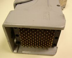
On the KI10, and KL10s with an external memory bus, the memory bus cables ended in a large QuickLatch connector; these connectors were also used on the CPU end of I/O bus cables of those machines.
See also
External links
- KL10-Based Technical Manual (EK-OKL10-TM-002) - the SBus is covered on pp. 76-80 of the PDF; the XBus is covered on pp. 59-76
- decsystem-1080/1090 System Description (EK-1080U-SD-003) - the SBus is covered on pp. 68-70 of the PDF
- KL10-Based Physical Description - has images of CJ dual card connectors and QuickLatch connectors, pp. 69-70
