DHV11 asynchronous serial line interface
The DHV11 asynchronous serial line interface is the first QBUS equivalent to the UNIBUS DH11. It provided 8 RS-232 asynchronous serial lines, with full modem control, depending on the cabling option chosen (below). Output used DMA (with each line having its own buffer pointer and count); input used a 256-character FIFO buffer.
It was later replaced by the DHQ11, which could be set to exactly emulate either the DHV11 or the DHU11.
Contents
Device registers
The registers in the DHV11 are somewhat different from those in the DH11:
- the QBUS has a larger address space than the UNIBUS, so it needs two word-sized registers to hold the output buffer address;
- the DHV11 includes several microprocessors, and has extended capabilities, including a diagnostic self-test, and hardware in-band flow control support (on both input and output);
- the DHV11 has the ability to transmit under program data movement.
| Register | Abbreviation | Address |
|---|---|---|
| Control and Status Register | CSR | 17760440 |
| Receive Buffer Register | RBUF | 17760442 |
| Transmit Character Register | TXC | 17760442 |
| Line Parameter Register | LPR | 17760444 |
| Line Status Register | STAT | 17760446 |
| Line Control Register | CTRL | 17760450 |
| Transmit Buffer Address Register Low | TBADL | 17760452 |
| Transmit Buffer Address Register Hi | TBADH | 17760454 |
| Transmit Buffer Count Register | TBCT | 17760456 |
The RBUF and TXC share an address; the RBUF is read only, and the TXC is write only. The TXC through TBCT are replicated, with one for each line in the device; the 'Line' field in the CSR indicates which one is currently available.
The addresses shown are for the first DHV11 in a system; additional ones are normally set to be at 17760460, 17760500.
Control and Status Register (CSR)
| TXA | TXIE | DF | TDE | Unused | Tx Line | RDA | RXIE | MR | Unused | Line | |||||
| 15 | 14 | 13 | 12 | 11 | 10 | 09 | 08 | 07 | 06 | 05 | 04 | 03 | 02 | 01 | 00 |
- TXA - Transmitter Action
- TXIE - Transmit Interrupt Enable
- DF - Diagnostic Fail
- TDE - Transmit DMA Error
- Tx Line - Line which set TXA
- RDA - Received Data Available
- RXIE - Receive Interrupt Enable
- MR - Master Reset
- Line - Select line register set (TXC through TBCT)
Line Parameter Register (LPR)
| TSpeed | RSpeed | STOP | EVEN | PARE | CLEN | DICD | Unused | ||||||||
| 15 | 14 | 13 | 12 | 11 | 10 | 09 | 08 | 07 | 06 | 05 | 04 | 03 | 02 | 01 | 00 |
- DICD - Diagnostic Code
- 00 - Normal operation
- 01 - Report status via the FIFO
Line Status Register (STAT)
| DSR | Unused | RI | DCD | CTS | Unused | DHU | Not Present | ||||||||
| 15 | 14 | 13 | 12 | 11 | 10 | 09 | 08 | 07 | 06 | 05 | 04 | 03 | 02 | 01 | 00 |
- DHU - DHU indication (always '0')
Line Control Register (CTRL)
| Unused | RTS | Unused | DTR | LTYP | MAINT | FXOFF | OAUTO | BREAK | RXE | IAF | TXA | ||||
| 15 | 14 | 13 | 12 | 11 | 10 | 09 | 08 | 07 | 06 | 05 | 04 | 03 | 02 | 01 | 00 |
- LTYP - Link Type
- MAINT - Maintenance Mode
- 00 - Normal operation
- 01 - Automatic echo mode
- 10 - Local loopback
- 11 - Remote loopback
- FXOFF - Force XOFF (on incoming traffic)
- OAUTO - Outgoing Auto-Flow (flow control)
- BREAK - Transmit Break
- RXE - Receiver Enable
- IAF - Incoming Auto-Flow (flow control)
- TXA - Transmit DMA Abort
Implementation
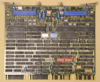
Physically, the DHV11 consisted of a single quad card, the M3104. It uses four Dual UART (DUART) chips, and connects to one or two distribution panels via flat cables plugged into Berg headers on edge of the card.
Cabling
There are two options for cabling to the DHV11; the first (usual) one provides full modem control, the second carries no modem control signals, and is thus only suitable for local terminals.
In the former, the DHV11 is connected to a pair of H3173-A distribution panels (4 lines each) via a BC05L flat cable, one per distribution panel; the BC05L connects to a 40-pin Berg header on each end. The H3173-A contains four male DB-25 connectors (DB-25P), i.e. wired as DTEs (most local terminals will therefore require a a null modem).
It can be recognized by the DEC part number 50-15588-01 or -02 on its PCB; the two versions differ in their layout, but have identical functionality, and are interchangeable. In addition to the usual '-xx' length indicators on the BC05L cable, it was also available in BC05L-1K (21 inch) and BC05L-2F (30 inch) lengths.
The alternative approach is the "remote distribution panel cabinet kit". In this, an intermediate "bulkhead panel" (H3176, PCB part number 50-16805) containing a single DB-25S female connector (not wired as an EIA port) is connected to the DHV11 via the usual flat cables; this is then connected externally via a BC22H 25-conductor external round cable to a "remote distribution panel" (H3175), which contains eight DB-25P male connectors (likely wired as DTEs, but the DEC documentation does not say so explicitly).
See also
External links
- DHV11 Technical Manual (EK-DHV11-TM-002)
- DHV11 Maintenance Card (EK-DHV11-MC)
- DHV11 Field Maintenance Print Set (MP01793)
- DHV11 (M3104)

