Difference between revisions of "BA23 Enclosure"
(give DEC formal name in intro; better flow there; tweak images a bit) |
m (+New category) |
||
| (13 intermediate revisions by 3 users not shown) | |||
| Line 2: | Line 2: | ||
The '''BA23 Enclosure''' is a [[QBUS]] [[mounting box]] from [[Digital Equipment Corporation|DEC]] which is available in pedestal, table-top, and rack mount versions. There is also a 'bigger brother', the [[BA123]] enclosure. | The '''BA23 Enclosure''' is a [[QBUS]] [[mounting box]] from [[Digital Equipment Corporation|DEC]] which is available in pedestal, table-top, and rack mount versions. There is also a 'bigger brother', the [[BA123]] enclosure. | ||
| + | |||
| + | The BA23 is the successor to the [[BA11-M mounting box|BA11-M]] QBUS mounting box. | ||
The BA23 enclosure is famous for the risk to skin one's knuckles - it is packed inside very tightly. | The BA23 enclosure is famous for the risk to skin one's knuckles - it is packed inside very tightly. | ||
| Line 7: | Line 9: | ||
==BA23 Usage== | ==BA23 Usage== | ||
| − | The BA23 enclosure was used for the following DEC [[PDP-11]] and [[MicroVAX]] computers: | + | The BA23 enclosure was used for the following DEC [[PDP-11]], [[VAXstation]], and [[MicroVAX]] computers: |
| − | * [[PDP-11/ | + | * [[PDP-11/23+]] |
| + | * [[PDP-11/53]] | ||
* [[PDP-11/73]] | * [[PDP-11/73]] | ||
* [[PDP-11/83]] | * [[PDP-11/83]] | ||
| Line 18: | Line 21: | ||
* [[MicroVAX II]] | * [[MicroVAX II]] | ||
* [[VAXstation II]] | * [[VAXstation II]] | ||
| − | * [[VAXstation 3200]] | + | * [[VAXstation 3200/3500 | VAXstation 3200]] |
Some versions of the computers listed above were also available in the BA123 enclosure, or in the [[H9642]] Medium System Cabinet. | Some versions of the computers listed above were also available in the BA123 enclosure, or in the [[H9642]] Medium System Cabinet. | ||
| Line 61: | Line 64: | ||
[[File:BA23 Signal Distribution Panel.png|300px|thumb|left|BA23 Signal Distribution Panel]] | [[File:BA23 Signal Distribution Panel.png|300px|thumb|left|BA23 Signal Distribution Panel]] | ||
| − | The signal distribution panel carries signals from an [[RQDX1]], [[RQDX2]], or [[RQDX3]] controller module in the [[QBUS#Variable_address_size|Q22-bus]] backplane to the mass storage devices. | + | The signal distribution panel carries signals from an [[RQDX1/RQDX2 MFM Disk & Floppy QBUS Controllers|RQDX1]], [[RQDX1/RQDX2 MFM Disk & Floppy QBUS Controllers|RQDX2]], or [[RQDX3 MFM Disk & Floppy QBUS Controller|RQDX3]] controller module in the [[QBUS#Variable_address_size|Q22-bus]] backplane to the mass storage devices. |
<br clear=all> | <br clear=all> | ||
| Line 76: | Line 79: | ||
<br clear=all> | <br clear=all> | ||
| + | |||
| + | ===Termination=== | ||
| + | |||
| + | The BA23 backplane includes removable SIP termination resistors at the bottom. Termination may be 120 ohms or 240 ohms, depending on processor board. Per [[MicroNote]] #35, "Backplane Expansion/Termination" (below), these termination packs are removed when an expansion chassis is used with the BA23. Keep this in mind when separating an expanded QBus system! | ||
==BA23 Internal Cabling== | ==BA23 Internal Cabling== | ||
| Line 106: | Line 113: | ||
You can increase the fan voltages to +12 Vdc by changing a power supply jumper. | You can increase the fan voltages to +12 Vdc by changing a power supply jumper. | ||
The [[KA630]] CPU module’s thermal and acoustical specifications for example, are based on the +10 volt setting. | The [[KA630]] CPU module’s thermal and acoustical specifications for example, are based on the +10 volt setting. | ||
| − | The required fan power does not affect the 230 W output. | + | The required fan power does not affect the 230 W output. |
| + | |||
| + | === Capacitor Issues === | ||
| + | |||
| + | The BA23 power supply contains one or more RIFA capacitors, which should be replaced before operation. These capacitors fail due to moisture ingress from cracks in the encapsulation. They release great quantities of smoke when they fail. | ||
| + | |||
| + | The BA23 power supply assembly AA12131, manufactured by Aztec, has been found with leaking general purpose and low ESR capacitors, and should be recapped when disassembled for RIFA replacement. The large capacitors in the fan supply circuit generally do not require replacement, nor do the bulk capacitors immediately after the AC line rectifiers. A capacitor list has been provided in the External Links section. | ||
==BA23 I/O Panel== | ==BA23 I/O Panel== | ||
| Line 141: | Line 154: | ||
You can install three more type A inserts by removing the bracket between the third and fourth cutouts and installing an adapter plate. | You can install three more type A inserts by removing the bracket between the third and fourth cutouts and installing an adapter plate. | ||
| + | |||
| + | ==Cooling Considerations== | ||
| + | |||
| + | The BA23 uses an airflow path which pulls cooling air through the card cage, into the [[power supply]], and exhausts it through the top (in vertical orientation) or left (horizontal orientation, from the front) side of the chassis through two 120V 120mm fans. The fan closest to the rear of the chassis is mostly responsible for power supply and [[QBUS]] card cage cooling, the fan closest to the front of the chassis handles storage area cooling. | ||
| + | |||
| + | Operating the BA23 with the I/O panel removed may reduce cooling efficiency, leading to hot running or overheating when running programs which stress the system, such as the [[XXDP diagnostic package|XXDP]] '''VMJAB0''' memory exerciser, especially in configurations that include a [[KDJ11-B CPU|KDJ11-B]]. The intake side of the chassis should be kept free from obstructions during operation, as the fans in the output side will pull intake air from the path of least resistance. | ||
| + | |||
| + | When operating the BA23 in a rack mounted configuration, ensure adequate intake and exhaust airflow. This often precludes the use of rack side skins. | ||
==External links== | ==External links== | ||
* [http://bitsavers.trailing-edge.com/scandocs.trailing-edge.com/micropdp11-volume_2_enclosures-EK-186AA-MG-001.pdf BA23 Enclosure Maintenance] (EK-186AA-MG-001) | * [http://bitsavers.trailing-edge.com/scandocs.trailing-edge.com/micropdp11-volume_2_enclosures-EK-186AA-MG-001.pdf BA23 Enclosure Maintenance] (EK-186AA-MG-001) | ||
| + | * [https://www.ibiblio.org/pub/academic/computer-science/history/pdp-11/hardware/micronotes/numerical/micronote35.txt Backplane Expansion/Termination] | ||
| + | * [http://filedump.glitchwrks.com/cap_lists/dec_ba23_aa12131.pdf DEC BA23 AA12131 Power Supply Capacitor List] | ||
| − | [[Category: DEC Hardware]] | + | [[Category: DEC Mounting Boxes]] |
| + | [[Category: QBUS Hardware]] | ||
Latest revision as of 15:14, 26 July 2024
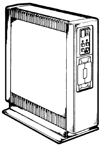
The BA23 Enclosure is a QBUS mounting box from DEC which is available in pedestal, table-top, and rack mount versions. There is also a 'bigger brother', the BA123 enclosure.
The BA23 is the successor to the BA11-M QBUS mounting box.
The BA23 enclosure is famous for the risk to skin one's knuckles - it is packed inside very tightly.
Contents
BA23 Usage
The BA23 enclosure was used for the following DEC PDP-11, VAXstation, and MicroVAX computers:
Some versions of the computers listed above were also available in the BA123 enclosure, or in the H9642 Medium System Cabinet.
The H9642 Medium System Cabinet contains two BA23 enclosures, one 'Standard' BA23-A, and one 'Expander' BA23-C.
In the cabinet both BA23 enclosures are connected with a BCV2A 'Qbus expansion cable and terminator BA23A to BA23C' to provide a large Qbus configuration.
BA23 Mass Storage Device Areas
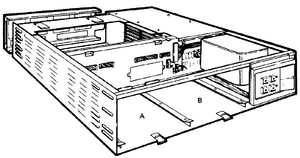
The BA23 can hold full-height and half-height 13.3 cm (5.25 in) mass storage devices, depending on the system.
You can install one RD5x-series fixed-disk drive and one removable-media drive — an RX50 diskette drive or a TK50 tape drive. You cannot install two full-height, fixed-disk drives due to power limitations.
You can connect external drives to the system’s I/O distribution panel.
The number of drives you can use depends on the space available in the I/O panel and backplane, and the amount of power available to run the drive controllers.
BA23 Control Panel
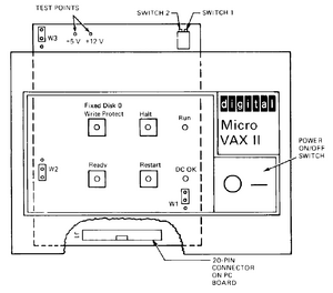
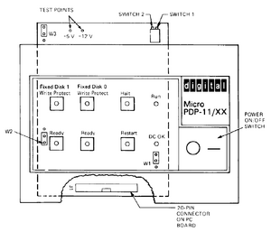
The BA23 has either a 4- or 6-button control panel as follows:
Systems with a 4-button control panel support only full-height mass storage devices.
Systems with a 6-button control panel support either full-height or half-height devices.
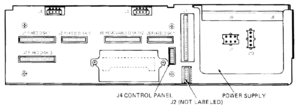
BA23 Signal Distribution Panel
The signal distribution panel carries signals from an RQDX1, RQDX2, or RQDX3 controller module in the Q22-bus backplane to the mass storage devices.
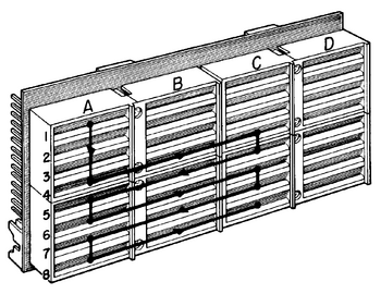
BA23 H9278 Backplane
The BA23 enclosure contains the H9278 Qbus backplane.
The picture shows the H9278 Qbus Backplane bus grant continuity.
Slots 1-3 are Q/CD; slots 4-8 are Q/Q
Termination
The BA23 backplane includes removable SIP termination resistors at the bottom. Termination may be 120 ohms or 240 ohms, depending on processor board. Per MicroNote #35, "Backplane Expansion/Termination" (below), these termination packs are removed when an expansion chassis is used with the BA23. Keep this in mind when separating an expanded QBus system!
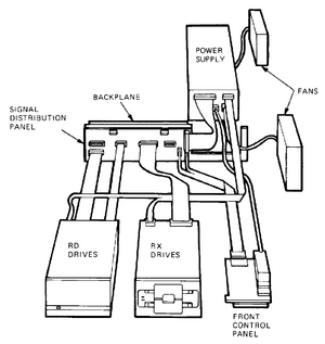
BA23 Internal Cabling
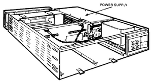
BA23 H7864 Power Supply
There are three variations of the BA23 power supply, depending on the enclosure model number: H7864, H7864A, or H7864B.
The power supply regulators maintain proper output voltages against temporary fluctuations in the ac input to the power supply.
The power supply is a 230 W unit. It supplies +5 Vdc at 4.5 amps (A) to 36.0 A, and +12 Vdc at 0.0 A to 7.0 A to the following system components:
- Backplane
- Fixed-disk drive
- Diskette drive or tape drive
The power supply also sends three system control signals to the backplane, asserting two of these signals (BDCOK H and BPOK H) when the system power is stable. The third signal (BEVENT L) is an external line clock interrupt request to the CPU. The LTC switch on the control panel PC board enables the BEVENT signal.
The power supply also has two +10 Vdc at 0.45 A fan outputs for the front and rear dc fans. You can increase the fan voltages to +12 Vdc by changing a power supply jumper. The KA630 CPU module’s thermal and acoustical specifications for example, are based on the +10 volt setting. The required fan power does not affect the 230 W output.
Capacitor Issues
The BA23 power supply contains one or more RIFA capacitors, which should be replaced before operation. These capacitors fail due to moisture ingress from cracks in the encapsulation. They release great quantities of smoke when they fail.
The BA23 power supply assembly AA12131, manufactured by Aztec, has been found with leaking general purpose and low ESR capacitors, and should be recapped when disassembled for RIFA replacement. The large capacitors in the fan supply circuit generally do not require replacement, nor do the bulk capacitors immediately after the AC line rectifiers. A capacitor list has been provided in the External Links section.
BA23 I/O Panel
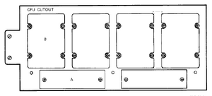
You use the I/O panel to connect external devices to the system.
Each device connects to a module in the system through a filtered connector.
You mount the connector on an insert, then install the insert in a cutout on the I/O panel.
Filtered connectors and inserts are part of the option’s cabinet kit.
Usually, the CPU insert is installed in the top (or left) cutout.
The I/O panel has six cutouts in two sizes, types A and B.
| BA23 I/O Panel Cutout and Insert Sizes | ||||
|---|---|---|---|---|
| Type | Quantity | C/I | Inches | Millimeters |
| A | 2 | Cutout | 0.6 x 3.2 | 15 x 81 |
| A | 2 | Insert | 1.0 x 4.0 | 25 x 102 |
| B | 4 | Cutout | 2.25 x 3.2 | 57 x 81 |
| B | 4 | Insert | 2.5 x 3.3 | 64 x 84 |
You can install three more type A inserts by removing the bracket between the third and fourth cutouts and installing an adapter plate.
Cooling Considerations
The BA23 uses an airflow path which pulls cooling air through the card cage, into the power supply, and exhausts it through the top (in vertical orientation) or left (horizontal orientation, from the front) side of the chassis through two 120V 120mm fans. The fan closest to the rear of the chassis is mostly responsible for power supply and QBUS card cage cooling, the fan closest to the front of the chassis handles storage area cooling.
Operating the BA23 with the I/O panel removed may reduce cooling efficiency, leading to hot running or overheating when running programs which stress the system, such as the XXDP VMJAB0 memory exerciser, especially in configurations that include a KDJ11-B. The intake side of the chassis should be kept free from obstructions during operation, as the fans in the output side will pull intake air from the path of least resistance.
When operating the BA23 in a rack mounted configuration, ensure adequate intake and exhaust airflow. This often precludes the use of rack side skins.
