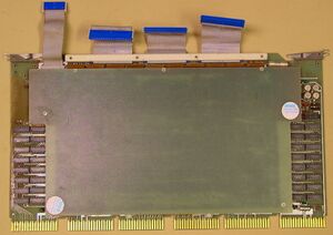
MM11-W core memory
The MM11-W was a fairly rare 64 Kbyte core main memory system for the later PDP-11 UNIBUS machines (it was a standard option on the PDP-11/60). An MM11-W was composed of a four board set:
- G116 - hex-width sense/inhibit module
- G236 - hex-width XY Drive, current source, decode module
- H224-D - hex-width core stack
- M8294 - quad-width timing and control module
The MM11-W required a custom nine-slot backplane (DEC part number 70-09295). The MF11-W was a backplane plus a single MM11-W board set; the backplane has room for one more MM11-W board set.
There was also a parity-capable variant, the MM11-WP, which added an dual-width M7259 Parity Control Module, and substituted an H224-C (with two more bits per word) for the H224-D. The MM11-WP required the -4 variant of the backplane; the non-parity version used the -3. (The MM11-U used a different version of the same backplane; the -1 for the MM11-U, and the -2 for the MM11-UP. The -1/-2 variants could be modified to a -3/-4 by the addition of 4 wire-wrap wires.)
The MM11-W also supported interleaving between a pair of MM11-W units.
The board set of the MM11-W (less the M8294) is also used in the MJ11 memory system, and (with the 19-bit wide H224-B variant of the core stack) in the MH10 core memory.
Contents
Module chart
The board organization in the MF11-W backplanes is (viewed from the module side of the backplane):
| Connector | ||||||
|---|---|---|---|---|---|---|
| Slot | A | B | C | D | E | F |
| 1 | UNIBUS In | M8294 Timing + Control | ||||
| 2 | M7259 Parity Controller | Unused | ||||
| 3 | G116 Sense/Inhibit | |||||
| 4 | H224-C/D Core stack | |||||
| 5 | G236 X/Y Driver | |||||
| 6 | G236 X/Y Driver | |||||
| 7 | H224-C/D Core stack | |||||
| 8 | G116 Sense/Inhibit | |||||
| 9 | UNIBUS Out | M8294 Timing + Control | ||||
The first MM11-W set normally goes in slots 6/7/8/9; when the second MM11-U set was added, it was normally installed in slots 1/3/4/5; the order could be reversed, though.
The H224-C/D is connected to the G116/G236 cards with 'over the back' flat cables, which carry the sense/inhibit signals from the core stack board to the electronics board. It is connected to the G236 with a 20-pin cable, and to the G116 with three 40-pin connectors. The cable end on the G116/G236 end is a standard Berg header, but on the H224-C/D end, the cables are soldered directly to the board, not plugged into a connector.
Parity and non-parity backplane configuration
Like the MM11-U, installing an MM11-W (non-parity) module set in an MF11-WP backplane will likely cause the machine to hang when that memory is referenced.
This is because during parity operation, the SSYN signal is routed through the M7259 parity controller board, and that only issues the SSYN once it has checked that the parity is OK. On non-parity installations, the 'proto-SSYN' from the rest of the memory is just hard-wired straight to the output to the UNIBUS.
That requires a jumper on the backplane for non-parity memory: it runs from pin B1U1 to B2U1. This jumper should not be present for parity memory. Note that therefore parity and non-parity memory cannot be mixed on the same backplane.
See also
Further reading
- MF11-W/WP user manual (EK-MF11W-OP)
- MF11-W/WP maintenance manual (EK-MF11W-MM)
- MF11-W/WP Field Maintenance Print Set (MP00034)
