PDP-11/60
The PDP-11/60 was, in its day, a rather unsuccessful model of DEC's PDP-11 line; although considerable more complex than the PDP-11/34, it did not have significant capability advantages over it.
In particular, it had the same limited memory management, without so-called 'I+D separatation', which therefore limited the size of the applications which could run on it; it also supported only the UNIBUS, which normally limited it to 248KB of main memory.
It is of interest now since it had an option to permit loadable microcode; it is a very rare machine, though, since its lack of commercial success meant very few were produced.
Hardware
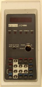
The PDP-11/60 is based around the KD11-K CPU. It provided the full FP11 floating point using microcode; as an option, the FP11-E Floating Point Processor, which provided a high-performance implementation as a co-processor, was also available.
A single slot in the CPU's backplane is available to hold either a User Control Store (1KW of read-write microcode), an Extended Control Store (1.5KW ROM microcode), or a Diagnostic Control Store.
Standard main memory was either MM11-WP core memory, or MF11S-KF MOS Memory.
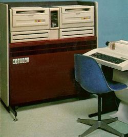
The -11/60 used swing-out BA11-P card cages to hold all its cards; generally a pair, one holding the CPU and device controllers, the other main memory and more controllers.
hampage.hu
Quote:1977. The /60 was an expensive "middle-class" machine, intended as the successor of the /40. It should have been introduced after the /70, but was delayed at least 12-18 months due design and debugging problems. It had a writable control store (WCS) for custom instructions, and floating point instructions were implemented in the CPU microcode. It also had 18-bit memory management. With the FPP option it had the best floating point performance among the -11's. As for packaging, it came in the "low boy/high boy" cabinets, the one pictured to the left is the "high" one. The storage devices could be placed in the upper region, the card cage itself was in the lower half.
External links
- PDP-11/60 - BitSavers
- PDP-11/60 installation and operation manual (EK-11060-OP-003)
- PDP-11/60 cabinet and power supply manual (EK-11060-SV-01)
- 11/60 Systems Field Maintenance Print Set (MP00166)
| v • d • e PDP-11 Computers and Peripherals |
|---|
| UNIBUS PDP-11s - PDP-11/20 • PDP-11/15 • PDP-11/35 • PDP-11/40 • PDP-11/45 • PDP-11/50 • PDP-11/55 • PDP-11/70 PDP-11/05 • PDP-11/10 • PDP-11/04 • PDP-11/34 • PDP-11/60 • PDP-11/44 • PDP-11/24 • PDP-11/84 • PDP-11/94 QBUS PDP-11s - PDP-11/03 • PDP-11/23 • PDP-11/23+ • MicroPDP-11/73 • MicroPDP-11/53 • MicroPDP-11/83 • MicroPDP-11/93 QBUS CPUs: LSI-11 • LSI-11/2 • KDF11-A • KDF11-B • KDJ11-A • KDJ11-B • KDJ11-D • KDJ11-E Buses: UNIBUS • UNIBUS map • SPC • MUD • EUB • QBUS • CD interconnect • PMI Also: PDP-11 architecture • PDP-11 Extended Instruction Set • FP11 floating point • PDP-11 Memory Management |
| UNIBUS CPUs: KA11 • KC11 • KB11-A • KB11-B • KB11-C • KB11-D • KD11-A • KD11-B • KD11-D • KD11-E • KD11-EA • KD11-K • KD11-Z • KDF11-U
Co-processors: FP11-A • FP11-B • FP11-C • FP11-E • FP11-F • KE44-A • FPF11 Chips: LSI-11 • KEV11-A • KEV11-B • KEV11-C • F-11 • KEF11-A • KTF11-A • T-11 • J-11 • FPJ11 CPU options: KE11-E • KE11-F • KJ11-A • KT11-C • KT11-D • KK11-A • KK11-B • KT24 • KTJ11-B Rare CPU options: KS11 Memory Protection and Relocation option • KT11-B Paging Option • KUV11 Writeable Control Store Front panels: KY11-A • KY11-D • KY11-J • KY11-LA • KY11-LB • KY11-P More on buses: UNIBUS and QBUS termination • Bus Arbitration on the Unibus and QBUS • CTI BUS PDT-11s - PDT-11/110 • PDT-11/130 • PDT-11/150 CTI PDP-11s - PRO-325 • PRO-350 • PRO-380 Other: FIS floating point • PDP-11 Commercial Instruction Set • PDP-11 stacks • PDP-11 family differences |

