FP11-A Floating-Point Processor
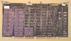
The FP11-A Floating-Point Processor is the optional hardware floating point unit for the PDP-11/34A (KD11-EA CPU). It consists of a single hex board, the M8267. It supports the full PDP-11 FP11 floating point.
The FP11-A uses a bank of 16 Am2901 Four-Bit Microprocessor Slice chips to perform all its computations; the main CPU is also used in floating point instructions, to load and store operands in main memory, etc. Both are microcoded; the microcode width is 48 bits in each.
The FP11-A's connections to the KD11-EA include two over the back connectors; a 20-pin connector to the M8265 card of the KD11-EA, and a 10 pin connector to the M8266 card. (This was likely because the PDP-11/34 could be field-upgraded from a KD11-E CPU, which did not support the floating point unit, to a KD11-EA, which did - but its original DD11-P backplane was retained.)
Implementation
The microcode to control the logic elements on the FP11-A is stored in PROM on the FP11-A; the microcode for floating point instructions in the CPU is contained on the CPU's M8266 card. The portion of the microcode there used for floating point instructions is the high half of the microcode address space, which is increased by one bit in the KD11-EA over that in the KD11-E. The microcode PROM chips in the KD11-EA are thus twice the size (1024.x4) of those in the KD11-E (512.x4).
Most bits (0 to 8) of the micro-PC (next micro-instruction) are generated in the KD11-EA, and sent to the FP11-A; the new high bit (9) is however generated in the FP11-A, and sent back to the KD11-EA. One of the Instruction Decoder PROMs in the KD11-EA is twice the size of that in the KD11-E; the extra address input to it is a signal which indicates that an FP11-A is installed. Thus, it is as if that chip contains two separate instruction decoding tables: one for use when no FP11-A in installed (and thus, floating point instructions will be designated as 'illegal'), and another one when it is.
Note that since bit 9 of the micro-PC is not generated in the KD11-EA (its microword does not contain a bit for it in the 'next micro-instruction' field), that Instruction Decoder cannot cause the microcode to branch to the floating point microcode. Instead (as described in section 6.4.1 of the FP11-A Technical Manual), when a new instruction is fetched, circuitry on the FP11-A checks to see if it is a floating point instruction, and if so, forces a microcode branch to 01400 (in the floating point microcode).
The PROMS in the FP11-A are only 512.x4; there are thus no FP11-A microcode words associated with the bottom half of the microcode address space (used for 'normal' instructions). As described in section 6.4.8 of the FP11-A Technical Manual, when the microcode in the bottom half is being executed, a signal disables the FP11-A microcode (so the FP11-A 'idles', and doesn't do anything).
Installation
This is mostly covered here. The latter over-the-top connector uses the connectors on the M8266 card which normally hold the maintenance cables to the KY11-LB Programmer's Console; in systems with a KY11-LB, the cables to the console will now connect to the M8267 card. (This is all necessitated because the FP11-A needs access to signals carried over the maintenance cables.)
For hardware debugging/repair, when the M8267 card is normally placed on a hex extender card to allow physical access to internal signals, a special W9042 Extender Board exists, to be used in place of the usual over the back connector, when so doing.
External links
- FP11-A floating-point processor user's guide (EK-FP11A-UG-001)
- FP11-A floating-point processor technical manual (EK-FP11A-TM-002)
- FP11-A Field Maintenance Print Set (MP00189) - contains the FP11-A microcode on pp. 42-89
