KL10
| KL10 | |
| Manufacturer: | Digital Equipment Corporation |
|---|---|
| Architecture: | PDP-10 |
| Year Design Started: | January, 1972 |
| Year First Shipped: | June, 1975 |
| Form Factor: | mainframe |
| Word Size: | 36 bits |
| Logic Type: | ECL ICs |
| Design Type: | clocked synchronous, microcoded |
| Microword Width: | 75 (Model A) 76 (Model B) |
| Microcode Length: | 1280 (Model A) 2K (Model B) |
| Clock Speed: | 50 MHz (Model A) 58 MHz (Model B) |
| Cache Size: | 2K words (KL10-PA and PV) 4K words (KL10-PW) |
| Memory Speed: | 1.0 μsec (initial core memory), 500 nsec (later MOS main memory) |
| Physical Address Size: | 22 bits |
| Virtual Address Size: | 18 bits (Model A) 23 bits (Model B) |
| Memory Management: | paging, 512-word pages |
| Operating System: | TOPS-10, TOPS-20, ITS, WAITS, TENEX, TYMCOM-X |
| Predecessor(s): | KI10 |
| Successor(s): | none |
| Price: | US$250K (CPU), US$600K-1.2M (system) |
The KL10 was the third generation of PDP-10 processors. It was built out of ECL, on hex cards. It was the first micro-programmed PDP-10 processor; the design was inspired by Stanford's Super Foonly.
The CPU had two main units, the 'E Box' ('Execution') and the 'M Box' ('Memory'). It provided three types of busses to the rest of the components of the system; the 'E Bus', from the E Box; and the 'S Bus' ('Storage'), and later the 'C Bus' ('Channel'), from the M Box. The S Bus (usually called the 'internal' memory bus) was for the attachment of main memory units, while the C Bus allowed DMA accesss to main memory.
(The S Bus was later modififed to a version called the 'X Bus', which was functionally the same as the S Bus, but used TTL signal voltages, instead of the ECL levels of the S Bus.)
A KL10 could support up to 4 DTE20 Ten-Eleven Interfaces; they allowed connection of a PDP-11 front end. At least one PDP-11, the 'master', was required; it could bootstrap the KL10, including loading the microcode.
A main memory cache for instruction and operand fetches, the MCA20 Cache - standard in some models, and optional in others - was available. Later in the KL10's life, the improved MCA25 KL Cache/Paging Upgrade, which increased both the size of both the main memory cache, and the paging cache, as well as improved the functionality of the latter, could be added/substituted for the MCA20.
A DMA20 Memory Bus Adapter could be attached to the S Bus, to provide up to 4 (in parallel, to increase memory bandwidth, as well as maximizing memory interleaving) KI10-compatible external memory busses (called the 'K Bus' in the KL10). Similarly, an DIA20 In/Out Bus Controller could be attached to the E Bus, to provide a PDP-10 I/O Bus (called the I Bus in the KL10).
The KL10 was used in the DECsystem-10 models 108x and 109x systems (initially with an external memory bus and an I/O bus, as a 'drop-in' processor replacement for a KI10), and in the high-end 20xx systems of the DECSYSTEM-20 line (with an internal memory bus).
Like its predecessor, the KI10, it was initially released in a single-processor version; a multi-processor version was released later (although only TOPS-10 ever supported it).
Devices
Up to 8 RH20 MASSBUS controllers could be installed; they connect to the E Bus (for control), and also to the C Bus (for data movement). The MASSBUS can be used to connect a variety of disk and magnetic tape mass storage devices.
Two optional high-speed data networking peripherals are also available:
- NIA20 Network Interconnect Adapter - an Ethernet interface
- CI20 Computer Interconnect - interface to the CI high-speed link
If either the NIA2O or CI20 in installed, since they use some of the backplane slots for the RH20's, only 4 RH20's may be installed if either is installed. They also connect to the EBUS and CBUS.
All low-speed devices were generally attached to the UNIBUS of one of the PDP-11 front ends (which could also be attached via a DL10); although the I Bus provided by a DIA20 was also an option.
Construction
There were two main packaging families: those used for the DECsystem-10, which used tall, medium-width cabinets like those of the KA10 and KI10, in the same turquoise blue as the latter; and the DECSYSTEM-20, which were shorter and wider and painted cream and orange.
The CPU, front end, and I/O controllers were accommodated in a set of three racks (or four, for some DECSYSTEM-20s); one to hold the CPU, one for the front-end, and one for all the I/O. The E Box and the M Box were both on the main backplane, in the CPU cabinet. The DMA20, DIA20, DTE20s and RH20s were all accommodated on backplanes in the second, I/O, cabinet; the first two were on a single backplane, and the latter two on another.
Versions
There were a number of variants over the lifetime of the KL10; the situation is confusing because there appear to be three different, somewhat orthogonal, namespaces for KL10 variants:
- CPU hardware variants (-PA, -PV and -PW);
- informal internal names for CPU variations ('Model A', 'Model B');
- KL10 'models' (-A through -E, and -R).
As far as is known, 'Model A' is an internal aphorism for -PA, and 'Model B' for -PV; the two are described in a DEC document as:
- "KL10-PA - A basic ECL processor with slots for cache and internal channels. Unofficially .. referred to as the Model A machine."
- "KL10-PV - A KL10-PA which has been modified to include extended addressing, more extensive microcode, and a faster clock. Unofficially .. referred to as the Model B machine."
The KL10-PV supported the 'Extended' PDP-10 architecture, with support for multiple 'sections' (256K-word address spaces), available to both the kernel and the user (although apparently only TOPS-20 supported the latter). The earlier machines could be field upgraded to a -PV, but it apparently needed a modified/new backplane.
Substitution/addition of the later MCA25 cache produced the KL10-PW; the resulting machine was named the 'Model C' by some.
Many of the 'models' (e.g. 'KL10-C' and 'KL10-D') appear to be names for particular configurations (with various options, such as the DMA20 and DIA20); here is a DEC table which (hopefully authoritatively) defines them:
| Model | PV | Cache | Int Chans | Max DTEs | Max RH20s | DIA | DMA |
|---|---|---|---|---|---|---|---|
| KL10-A | No | Yes | No | 1 | 0 | Yes | Yes |
| KL10-B | No | Yes | Yes | 4 | 8 | Yes | Yes |
| KL10-C | No | Optional | Yes | 4 | 8 | No | No |
| KL10-D | Yes | Yes | Yes | 4 | 8* | Yes | Yes |
| KL10-E | Yes | Optional | Yes | 4 | 8* | Optional | Optional |
| KL10-R | Yes | Optional | Yes | 4 | 8* | Optional | Optional |
(*: Maximum 4 RH20s if a CI20 or NIA20 is installed, as those use the slots for RH4-7 in the RH20 backplane.)
The 'KL10-R' appears to be a KL10-E in a new cabinet design, one compliant with newer FCC RFI emissions standards; but it may also refer to systems with the MCA25.
Note that the early KL10-A only supported a single DTE20, and no RH20s, and it was the later KL10-B and up (the first two also with the Model A CPU), which supported up to 4 DTE20s and up to 8 RH20s. This is because the I/O backplanes in the second bay of the CPU differed in the KL10-B and up, to support the larger I/O configuration. (The DTE20 backplane differed between the two.) The KL10-A was intended to replace KA10 and KI10 processors, hence the lack of support for RH20s, etc.
One significant division between KL-based systems is between those with an external memory bus (K bus), and those with an internal memory bus (the native S/X Bus).
The DEC numeric model numbers - a fourth namespace - are even more confused, since a 1090 could be either a "KL10-B(PA) or KL10-D(PV)"; similarly, the 2040 and 2050 could be a "KL10-C(PA) or KL10-E(PV)".
Well-known KL10's
There was a single KL10 ITS machine, MIT-MC, a very early Model A. It was later renamed to MX after a KS10 took the 'MC' identity, and was finally shut down in 1988; it is now in storage at the Living Computer Museum.
The SAIL (or SU-AI) time-sharing system — WAITS — main computer was a KL10 from 1976 to 1991. In 1983, it was upgraded from a model A to a model B CPU. Near the end, failing insulation in the backplane was fixed by inserting toothpicks.
External Links
- KL10 - documentation at Bitsavers
- KL10-Based Technical Manual (EK-OKL10-TM-002) - good detailed overview
- decsystem-1080/1090 System Description (EK-1080U-SD-003) - good medium-level description of the functionality of the KL10 CPU and its peripherals
- KL10-Based Physical Description (EK-108OU-PD-002) - contains KL10 board configuration, pp. 3-29
- KL10 Project Technology Goals - interesting memo discussing the analog aspects of the chip technology used in the KL10
- Digital's DECSYSTEM-20 - Part 5 - CPU (KL10)
- Corestore collection: DECSYSTEM 2065 KL10-RH - Good images, has two MG20 memory units
- KL-10
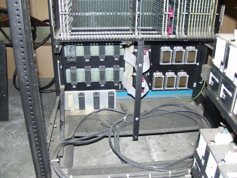
- KL10 I/O connectors - Good image of bus connectors: on the bottom, MASSBUS connectors on the left; memory and I/O bus QuickLatch connectors on the right
- PDP-11/40 - good images of a KL10 front end
- KL-10D Module Utilization
- KL - some interesting discussion of KL10 details
- SAIL Farewell - a good thumbnail history
- KL10 ITS microcode