Difference between revisions of "VAX-11/750"
(→VAX-11/750 images: "Cable Routing inside VAX-11/750" added) |
(→VAX-11/750 images: Added cable details) |
||
| Line 82: | Line 82: | ||
Left of card cage: | Left of card cage: | ||
* Top: 54-13489 - [[TU58]] controller | * Top: 54-13489 - [[TU58]] controller | ||
| − | * Bottom: H7112 - VAX-11/780 / VAX-11/750 Battery Backup Unit | + | * Bottom: [[H7112]] - VAX-11/780 / VAX-11/750 Battery Backup Unit |
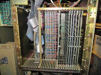
Inside card cage: | Inside card cage: | ||
| Line 108: | Line 108: | ||
<br clear=all> | <br clear=all> | ||
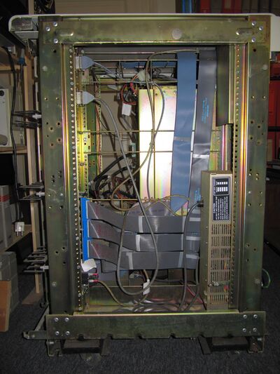
[[File:VAX-11750_Cable_Routing.JPG|400px|thumb|left|Cable Routing inside VAX-11/750 (left side open)]] | [[File:VAX-11750_Cable_Routing.JPG|400px|thumb|left|Cable Routing inside VAX-11/750 (left side open)]] | ||
| − | + | Round cables top left: | |
| − | * | + | * Console |
| − | * | + | * Remote Diagnose Modem |
| − | + | ||
| − | + | Cables bottom left to top right: | |
| − | ** | + | * [[DMF32]] [[Unibus]] Combo Module (3 flat cables) |
| − | * | + | * [[TU80K]] [[TU80]] Tape Adapter (2 flat cables, one behind the other) |
| − | * | + | * [[DEUNA]] Ethernet Adapter (round cable) |
| + | |||
| + | Bottom right: | ||
| + | * H7112 - VAX-11/780 / VAX-11/750 Battery Backup Unit | ||
<br clear=all> | <br clear=all> | ||
Revision as of 07:32, 2 June 2022
| VAX-11/750 | |
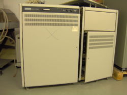 VAX-11/750 | |
| Codename: | Comet |
|---|---|
| Year Introduced: | October 1980 |
| RAM: | Max of 14 MB |
| VUPS: | 0.65 |
The VAX-11/750 (also known as the VAX/750) is a slower, more compact, but less expensive version of the VAX-11/780. It was built around the CPU/Memory Interconnect bus (CMI); the mandatory major CMI sub-systems (and components thereof) were:
It was codenamed 'Comet' by DEC. One of the first OS's available for the 750 was 4.1 BSD. According to 'Quarter Century of UNIX', the DoD could purchase 6 750's for about $150,000 USD.
Contents
CMI Options
The CMI was instantiated as a large backplane; option slots in the backplane can be used for a variety of optional adapters:
- RH750 Massbus Adapter - L0007
- CI750 Computer Interconnect Interface (CI)
- DW750 Second Unibus Interface
- DR750 Parallel Interface
Allowable Configurations of CMI Slots 7, 8, & 9 are:
| Slot 7 | Slot 8 | Slot 9 |
|---|---|---|
| RH750 | RH750 | RH750 |
| DW750 | RH750 | RH750 |
| DR750 | RH750 | RH750 |
| DW750 | DR750 | RH750 |
| DW750 | CI750 | RH750 |
| CI750 | RH750 | RH750 |
NOTES:
- Combination of DR750 and CI750 is not allowed
- Only one DR750 per system is allowed
- Only one DW750 per system is allowed
- Only one CI750 per system is allowed
CMI backplane configuration
| Slot | Contents |
|---|---|
| 1 | L0001 Floating-Point Accelerator (FPA) |
| 2 | L0002 Data Path Module (DPM) |
| 3 | L0003 Memory Interconnect (MIC) |
| 4 | L0004 UNIBUS Interface (UBI) |
| 5 | L0005 CPU Control Store (CCS) |
| 6 | L0006 Remote Diagnostic Module (RDM) |
| 7 | CMI Option |
| 8 | CMI Option |
| 9 | CMI Option |
| 10 | L0011/L0016/L0022 Memory Controller (MCM) |
VAX-11/750 images
Left of card cage:
Inside card cage:
- Left: DD11-DK Unibus Backplane (with cards)
- Center: Memory Backplane (with cards)
- Right: CMI Backplane (with cards)
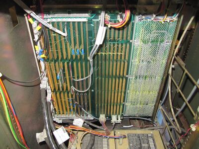
Backplanes:
- Left: CMI Backplane
- Center: Memory Backplane
- Right: DD11-DK - Unibus Backplane
- Lower left corner: 5V and 2.5V Power Supply cables (as thick as a finger!)
- Bottom: 5V and 2.5V Power Supplies
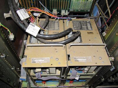
Power Supplies:
- Left: H7104-C 2.5V, 85A max.
- Right: H7104-D 5V, 135A max.
Round cables top left:
- Console
- Remote Diagnose Modem
Cables bottom left to top right:
- DMF32 Unibus Combo Module (3 flat cables)
- TU80K TU80 Tape Adapter (2 flat cables, one behind the other)
- DEUNA Ethernet Adapter (round cable)
Bottom right:
- H7112 - VAX-11/780 / VAX-11/750 Battery Backup Unit
See also
External links
- VAX Hardware Handbook Volume 1 - the VAX-11/750 is covered in Chapter 4 (pp. 154-171 of the PDF)
- VAX Maintenance Handbook: VAX-11/750 (EK-VAXV3-HB-001)
- VAX/750 - documentation at Bitsavers
- 11/750 Field Maintenance Print Set (MP01377)
- Vax 11/750 Frequently Asked Questions
- VAX-11/750
- Makings of a Comet: The VAX 11/750
| v • d • e VAX Computers and Operating Systems |
|---|
| VAX-11/7xx (including VAX 86x0) - VAX-11/780 • VAX-11/785 • VAX-11/750 • VAX-11/730 • VAX-11/725 • VAX 8600 • VAX 8650
VAX 8000 series (excluding VAX 86x0, above) - VAX 82xx/83xx series • VAX 85xx/87xx/88xx series MicroVAXen (many types also come in VAXserver and VAXstation models) - MicroVAX I • MicroVAX II VAXstation Series - VAXstation I • VAXstation II Late Model VAXen - VAX 4000 series • VAX 6000 series • VAX 7000 series • VAX 9000 series • VAX 10000 series |
| Special Purpose VAXen - VAXft series • rtVAX series • Infoserver series
Clones - CM 1700 • TPA-11/580 |
