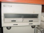
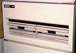
RX01/02 floppy drive
The RX01 and RX02 floppy drives were DEC's first floppy drives, and were used on a number of computers, such as the PDP-8 and PDP-11. They used 8" floppies, compatible with the IBM 3740 floppy drive; the media were single-sided, single-density, floppies, which came pre-formatted. (The RX0x drives are not capable of formatting blank floppies.) Data was protected with a CRC, compatible with that used by the IBM 3740.
The drives are mostly identical, except that the RX02 supports optional double-density operation. This double-density is not the same as the 'normal' double-density 8" floppy, but a unique-to-DEC format. Both drives provide 26 sectors per track (1-26), and 77 tracks per floppy (0-76), for a total of 2002 sectors. Single-density sectors hold 128 bytes, and double-density sectors hold 256 bytes, for a maximum total capacity of 256KB for the RX01, and 512KB for the RX02.
Single-density recording uses a double frequency (FM) coding (compatible with IBM 3740 devices), and double-density uses a modified Miller code (MFM). In an especially bizarre design choice, in both single- and double-density media, the sector headers are all recorded using FM coding; on double-density media, the data portions of sectors are recorded with MFM.
The RX02 included the M7744 Controller and M7745 Read-Write card. Each drive cabinet holds a pair of drives.
Both drives have UNIBUS and QBUS controllers; the RX11 and RX211 for the UNIBUS, and RXV11 and RXV21 for the QBUS. The first of each pair are for the RX01, and are programmed I/O; the latter are for the RX02, and provide DMA data transfer.
There are also as RK8E (RX01 only) and RK28 controllers for the PDP-8. The maximum number of drives supported by a single controller is two. The RX02 can be strapped to emulate an RX01, in which case the RX01 controllers (RX11 and RXV11) can support them.
These drives were used as primary mass storage devices for later low-cost PDP-11 systems, such as the LSI-11, and as such as 'console' floppies for the LSI-11 console computer in the VAX 11/780.
Coding systems
In the single-density double frequency (FM) coding, there is a flux reversal every clock time, and an additional flux reversal in the middle of the bit for a '1' bit; for '0' bits, there is no flux reversal. In the double-density Miller coding (MFM), a flux reversal indicates a '1' bit, and no flux reversal indicates a '0'; a clock is recorded only between data 'zeros'.
Since the maximum flux reversal rates are the same for FM, and MFM with a data rate double that of the FM, the same hardware can thus hold twice as many bits with the MFM coding.
The actual MFM encoding used is modified slightly to prevent a false sector header preamble (in FM coding) from being created within a double density data area (in MFM).
Layout
DEC normally left track 0 unused (to hold bootstraps). They also used an idiosyncratic layout of the 'logical' sectors on a floppy, intended to maximize the performance: the first logical sector of each data track was offset by six 'physical' sectors from the 'first' sector of the preceding track.
Specifications
- Seek error rate - 1 in 16 seeks
- Soft data error rate - 1 in 109 bits read or written
- Hard data error rate - 1 in 1012 bits read or written
- Data transfer rate
- Diskette to controller buffer - 4 usec/data bit (FM); 2 usec/data bit (MFM)
- Buffer to CPU interface - 1.2 usec/bit
- Track-to-track move - 6 msec/track maximum
- Head settle time - 25 msec maximum
- Rotational speed - 360 rpm ± 2.5%; 166 ms/rev nominal
- Bit density maximum (on inner track) - 3200 bpi (FM) or modified (MFM)
- Track density - 48 tracks/inch
- Average access - 262 ms, computed as follows:
- Seek - 77 tks/3 X 6 msec = 154 msec
- Settle - 25 msec
- Rotate - 166 msec/2 = 83 msec
| v • d • e PDP-11 Computers and Peripherals |
|---|
| UNIBUS PDP-11s - PDP-11/20 • PDP-11/15 • PDP-11/35 • PDP-11/40 • PDP-11/45 • PDP-11/50 • PDP-11/55 • PDP-11/70 PDP-11/05 • PDP-11/10 • PDP-11/04 • PDP-11/34 • PDP-11/60 • PDP-11/44 • PDP-11/24 • PDP-11/84 • PDP-11/94 QBUS PDP-11s - PDP-11/03 • PDP-11/23 • PDP-11/23+ • MicroPDP-11/73 • MicroPDP-11/53 • MicroPDP-11/83 • MicroPDP-11/93 QBUS CPUs: LSI-11 • LSI-11/2 • KDF11-A • KDF11-B • KDJ11-A • KDJ11-B • KDJ11-D • KDJ11-E Buses: UNIBUS • UNIBUS map • SPC • MUD • EUB • QBUS • CD interconnect • PMI Also: PDP-11 architecture • PDP-11 Extended Instruction Set • FP11 floating point • PDP-11 Memory Management |
| UNIBUS CPUs: KA11 • KC11 • KB11-A • KB11-B • KB11-C • KB11-D • KD11-A • KD11-B • KD11-D • KD11-E • KD11-EA • KD11-K • KD11-Z • KDF11-U
Co-processors: FP11-A • FP11-B • FP11-C • FP11-E • FP11-F • KE44-A • FPF11 Chips: LSI-11 • KEV11-A • KEV11-B • KEV11-C • F-11 • KEF11-A • KTF11-A • T-11 • J-11 • FPJ11 CPU options: KE11-E • KE11-F • KJ11-A • KT11-C • KT11-D • KK11-A • KK11-B • KT24 • KTJ11-B Rare CPU options: KS11 Memory Protection and Relocation option • KT11-B Paging Option • KUV11 Writeable Control Store Front panels: KY11-A • KY11-D • KY11-J • KY11-LA • KY11-LB • KY11-P More on buses: UNIBUS and QBUS termination • Bus Arbitration on the Unibus and QBUS • CTI BUS PDT-11s - PDT-11/110 • PDT-11/130 • PDT-11/150 CTI PDP-11s - PRO-325 • PRO-350 • PRO-380 Other: FIS floating point • PDP-11 Commercial Instruction Set • PDP-11 stacks • PDP-11 family differences |

