Difference between revisions of "PDP-11/05"
(→Original version: Add slot info, type 1/2 nomenclature) |
(→Backplane versions: Intergrate into existing content) |
||
| Line 26: | Line 26: | ||
===Original version=== | ===Original version=== | ||
| − | The original /05 and /10 came with backplanes wired to hold [[MM11-L core memory|MM11-L]] 16 Kbyte [[core memory]] units. There were two different backplanes: one (called "Configuration 1" in DEC documentation) held two memory units, with one slot left for [[Small Peripheral Controller|SPC]] devices; the other ("Configuration 2") held one memory unit, and provided four SPC slots. | + | The original /05 and /10 came with backplanes wired to hold [[MM11-L core memory|MM11-L]] 16 Kbyte [[core memory]] units. There were two different backplanes: one (called "Configuration 1" in [[Digital Equipment Corporation|DEC]] documentation) held two memory units, with one slot left for [[DEC card form factor|quad-height]] [[Small Peripheral Controller|SPC]] devices; the other ("Configuration 2") held one memory unit, and provided four SPC slots. |
| − | Here are the slot assignments in the backplanes | + | Here are the slot assignments in the backplanes (as seen from the board insertion side of the backplane, not the [[wire-wrap]] pin side, as is common in DEC documentation) : |
Configuration 1: | Configuration 1: | ||
| Line 37: | Line 37: | ||
! Slot !! A !! B !! C !! D !! E !! F | ! Slot !! A !! B !! C !! D !! E !! F | ||
|- | |- | ||
| − | | 1 || colspan="6" style="text-align:center;" | M7260 | + | | 1 || colspan="6" style="text-align:center;" | M7260 CPU board #0 |
|- | |- | ||
| 2 || colspan="6" style="text-align:center;" | M7261 CPU board #1 | | 2 || colspan="6" style="text-align:center;" | M7261 CPU board #1 | ||
| Line 79: | Line 79: | ||
| 8 || KM11-1 || KM11-2 || colspan="4" | SPC | | 8 || KM11-1 || KM11-2 || colspan="4" | SPC | ||
|- | |- | ||
| − | | 9 || colspan="2" | DF11 || colspan="4" | SPC | + | | 9 || colspan="2" | [[DF11 Communications Line Adapter]] || colspan="4" | SPC |
|} | |} | ||
| − | Note that the slots are numbered from 1 at the start; this is the inverse of the numbering in some DEC documentation. | + | Note that the slots are numbered from 1 at the start; this is the inverse of the numbering for these backplanes in some DEC documentation. |
===-N type=== | ===-N type=== | ||
| − | The /05N and /10N had a slightly different backplane, which had space for two MM11-L memory units, but deleted the SPC slot of the previous double MM11-L backplane, and replaced it with a slot to hold the | + | The /05N and /10N had a slightly different backplane, which had space for two MM11-L memory units, but deleted the SPC slot of the previous double MM11-L backplane, and replaced it with a slot to hold the dual-height M9970 console terminal cable board, and also a dual-height DF11. |
| − | Board locations (as seen from the board insertion side of the backplane | + | Board locations (again, as seen from the board insertion side of the backplane) are: |
{| class="wikitable" | {| class="wikitable" | ||
| Line 113: | Line 113: | ||
| 9 || colspan="2" | UNIBUS Out || colspan="4" style="text-align:center;" | H213/H214 Core stack | | 9 || colspan="2" | UNIBUS Out || colspan="4" style="text-align:center;" | H213/H214 Core stack | ||
|} | |} | ||
| + | |||
| + | Note that the two KM11 slots are at the other side of the backplane from the slots used for them in the 'Configuration 1' and 'Configuration 2' backplanes. | ||
===-S type=== | ===-S type=== | ||
Revision as of 01:02, 22 March 2019
| PDP-11/05 | |
| Manufacturer: | Digital Equipment Corporation |
|---|---|
| Architecture: | PDP-11 |
| Year Introduced: | June 1972 |
| Word Size: | 16 bit |
| Physical Address Size: | 18 bits (only 16 bits usable) |
| Bus Architecture: | UNIBUS |
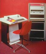
The PDP-11/05 was the fourth model in the PDP-11 series, following the PDP-11/20, the PDP-11/45 and the PDP-11/40; it used the KD11-B CPU. It was intended as a cost-reduced low-end machine to replace the PDP-11/20. Like all the other early PDP-11's, it was a UNIBUS machine.
The PDP-11/05 was absolutely identical to the PDP-11/10; the only difference between the /05 and the /10 was the number on the front panel. The /05 was aimed toward the OEM market, while the /10 was intended for end-users. General usage (following DEC's lead) is to refer to all these machines as '11/05's.
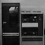
The earliest units came in a 5-1/4" box, which had room for only a double system unit backplane. A later version, the /05N and /10N, came in a 10-1/2" BA11-D Mounting Box; the final /05S and /10S versions came in the 10-1/2" BA11-K Mounting Box.
Backplane versions
The PDP-11/05 and /10 came in three versions, with four different versions of the main backplane (the 9-slot system unit holding the two CPU cards).
Original version
The original /05 and /10 came with backplanes wired to hold MM11-L 16 Kbyte core memory units. There were two different backplanes: one (called "Configuration 1" in DEC documentation) held two memory units, with one slot left for quad-height SPC devices; the other ("Configuration 2") held one memory unit, and provided four SPC slots.
Here are the slot assignments in the backplanes (as seen from the board insertion side of the backplane, not the wire-wrap pin side, as is common in DEC documentation) :
Configuration 1:
| Connector | ||||||
|---|---|---|---|---|---|---|
| Slot | A | B | C | D | E | F |
| 1 | M7260 CPU board #0 | |||||
| 2 | M7261 CPU board #1 | |||||
| 3 | G110 Memory Control | |||||
| 4 | G231 Memory Driver | |||||
| 5 | UNIBUS Terminator | H213/H214 Core stack | ||||
| 6 | G110 Memory Control | |||||
| 7 | G231 Memory Driver | |||||
| 8 | UNIBUS Out | H213/H214 Core stack | ||||
| 9 | KM11-1 | KM11-2 | SPC | |||
Configuration 2:
| Connector | ||||||
|---|---|---|---|---|---|---|
| Slot | A | B | C | D | E | F |
| 1 | M7260 CPU board #0 | |||||
| 2 | M7261 CPU board #1 | |||||
| 3 | G110 Memory Control | |||||
| 4 | G231 Memory Driver | |||||
| 5 | UNIBUS Terminator | H213/H214 Core stack | ||||
| 6 | Unused | SPC | ||||
| 7 | UNIBUS Out | SPC | ||||
| 8 | KM11-1 | KM11-2 | SPC | |||
| 9 | DF11 Communications Line Adapter | SPC | ||||
Note that the slots are numbered from 1 at the start; this is the inverse of the numbering for these backplanes in some DEC documentation.
-N type
The /05N and /10N had a slightly different backplane, which had space for two MM11-L memory units, but deleted the SPC slot of the previous double MM11-L backplane, and replaced it with a slot to hold the dual-height M9970 console terminal cable board, and also a dual-height DF11.
Board locations (again, as seen from the board insertion side of the backplane) are:
| Connector | ||||||
|---|---|---|---|---|---|---|
| Slot | A | B | C | D | E | F |
| 1 | DF11 | M9970 | KM11-A | KM11-B | ||
| 2 | M7260 | |||||
| 3 | M7261 | |||||
| 4 | UNIBUS Terminator | H213/H214 Core stack | ||||
| 5 | G110 Memory Control | |||||
| 6 | G231 Memory Driver | |||||
| 7 | G110 Memory Control | |||||
| 8 | G231 Memory Driver | |||||
| 9 | UNIBUS Out | H213/H214 Core stack | ||||
Note that the two KM11 slots are at the other side of the backplane from the slots used for them in the 'Configuration 1' and 'Configuration 2' backplanes.
-S type
The /05S and /10S came with a backplane wired to hold an MM11-U 32 Kbyte core memory, and which provided three SPC slots.
Keys
Unlike all the other keyed PDP-11s, which use a circular Ace key, the /05's (and /10s) use a normal flat Yale-type key. The original key is a Chicago Lock Company key, code "GRB 2"; this is cut 215, on a Chicago K5K or Ilco S1041T blank. If simply duplicating an existing key, Hillman Y11 and FR4 blanks may be used (both work, but one has to be trimmed a bit, length-wise).
Gallery
| v • d • e PDP-11 Computers and Peripherals |
|---|
| UNIBUS PDP-11s - PDP-11/20 • PDP-11/15 • PDP-11/35 • PDP-11/40 • PDP-11/45 • PDP-11/50 • PDP-11/55 • PDP-11/70 PDP-11/05 • PDP-11/10 • PDP-11/04 • PDP-11/34 • PDP-11/60 • PDP-11/44 • PDP-11/24 • PDP-11/84 • PDP-11/94 QBUS PDP-11s - PDP-11/03 • PDP-11/23 • PDP-11/23+ • MicroPDP-11/73 • MicroPDP-11/53 • MicroPDP-11/83 • MicroPDP-11/93 QBUS CPUs: LSI-11 • LSI-11/2 • KDF11-A • KDF11-B • KDJ11-A • KDJ11-B • KDJ11-D • KDJ11-E Buses: UNIBUS • UNIBUS map • SPC • MUD • EUB • QBUS • CD interconnect • PMI Also: PDP-11 architecture • PDP-11 Extended Instruction Set • FP11 floating point • PDP-11 Memory Management |
| UNIBUS CPUs: KA11 • KC11 • KB11-A • KB11-B • KB11-C • KB11-D • KD11-A • KD11-B • KD11-D • KD11-E • KD11-EA • KD11-K • KD11-Z • KDF11-U
Co-processors: FP11-A • FP11-B • FP11-C • FP11-E • FP11-F • KE44-A • FPF11 Chips: LSI-11 • KEV11-A • KEV11-B • KEV11-C • F-11 • KEF11-A • KTF11-A • T-11 • J-11 • FPJ11 CPU options: KE11-E • KE11-F • KJ11-A • KT11-C • KT11-D • KK11-A • KK11-B • KT24 • KTJ11-B Rare CPU options: KS11 Memory Protection and Relocation option • KT11-B Paging Option • KUV11 Writeable Control Store Front panels: KY11-A • KY11-D • KY11-J • KY11-LA • KY11-LB • KY11-P More on buses: UNIBUS and QBUS termination • Bus Arbitration on the Unibus and QBUS • CTI BUS PDT-11s - PDT-11/110 • PDT-11/130 • PDT-11/150 CTI PDP-11s - PRO-325 • PRO-350 • PRO-380 Other: FIS floating point • PDP-11 Commercial Instruction Set • PDP-11 stacks • PDP-11 family differences |


