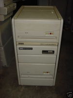
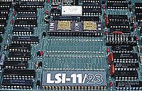
PDP-11/23
The PDP-11/23 was the second QBUS PDP-11 system; it used the KDF11-A CPU (M8189).
hampage.hu
Quote: Introduced in 1979. Intended as the successor of the PDP-11/03. Based on the F-11 chip set, it had a dual-height KDF11-A CPU card. The memory management was 22 bit (4MB address space), but in some revisions (KDF11-A Rev. A) only 18 lines were used. The LSI-11/23 instruction set consists of 97 standard and 46 optional floating point instructions. The microcycle time of the CPU is around 300 ns.
The PDP-11/23-PLUS used the quad-height KDF11-B CPU module, which had two asynchronous serial lines and boot PROMs on-board.
The KDF11-A module has four 40-pin sockets for the chipset. One is for the DCF11 two-chip hybrid (21-15541AB data path and 23-001C7 control chip), one's for the KTF11 MMU option and one's for the KEF11 floating-point option (another two-chip carrier; the MMU chip must be installed to use the FPP option). The remaining socket can be used with the CIS option, which spans two sockets wide (so you loose the FPP). The KDF11-B has five sockets, so there are no problems with this.
In floating-point-heavy applications, the FPF11 can be used. This is a quad-height module that is connected to the KEF11-socket on CPU board with a cable. It's based on bitslice processors, the performance is six times of the performance of the KEF11 option. (64-bit data path, 17-digit accuracy)
Gallery
More images here.
| v • d • e PDP-11 Computers and Peripherals |
|---|
| UNIBUS PDP-11s - PDP-11/20 • PDP-11/15 • PDP-11/35 • PDP-11/40 • PDP-11/45 • PDP-11/50 • PDP-11/55 • PDP-11/70 PDP-11/05 • PDP-11/10 • PDP-11/04 • PDP-11/34 • PDP-11/60 • PDP-11/44 • PDP-11/24 • PDP-11/84 • PDP-11/94 QBUS PDP-11s - PDP-11/03 • PDP-11/23 • PDP-11/23+ • MicroPDP-11/73 • MicroPDP-11/53 • MicroPDP-11/83 • MicroPDP-11/93 QBUS CPUs: LSI-11 • LSI-11/2 • KDF11-A • KDF11-B • KDJ11-A • KDJ11-B • KDJ11-D • KDJ11-E Buses: UNIBUS • UNIBUS map • SPC • MUD • EUB • QBUS • CD interconnect • PMI Also: PDP-11 architecture • PDP-11 Extended Instruction Set • FP11 floating point • PDP-11 Memory Management |
| UNIBUS CPUs: KA11 • KC11 • KB11-A • KB11-B • KB11-C • KB11-D • KD11-A • KD11-B • KD11-D • KD11-E • KD11-EA • KD11-K • KD11-Z • KDF11-U
Co-processors: FP11-A • FP11-B • FP11-C • FP11-E • FP11-F • KE44-A • FPF11 Chips: LSI-11 • KEV11-A • KEV11-B • KEV11-C • F-11 • KEF11-A • KTF11-A • T-11 • J-11 • FPJ11 CPU options: KE11-E • KE11-F • KJ11-A • KT11-C • KT11-D • KK11-A • KK11-B • KT24 • KTJ11-B Rare CPU options: KS11 Memory Protection and Relocation option • KT11-B Paging Option • KUV11 Writeable Control Store Front panels: KY11-A • KY11-D • KY11-J • KY11-LA • KY11-LB • KY11-P More on buses: UNIBUS and QBUS termination • Bus Arbitration on the Unibus and QBUS • CTI BUS PDT-11s - PDT-11/110 • PDT-11/130 • PDT-11/150 CTI PDP-11s - PRO-325 • PRO-350 • PRO-380 Other: FIS floating point • PDP-11 Commercial Instruction Set • PDP-11 stacks • PDP-11 family differences |


